A psychological pressure relief boxing receptor swing part and its production and assembly equipment

A technology for assembling equipment and swinging devices, which is applied in the direction of sports accessories, etc., can solve the problems of easily rebounding and hurting users, affecting user experience, and different rebounding strengths

Active Publication Date: 2022-05-17
岳阳职业技术学院
View PDF9 Cites 0 Cited by
  • Summary
  • Abstract
  • Description
  • Claims
  • Application Information

AI Technical Summary

Problems solved by technology

[0003] The technical problem to be solved by the present invention is: the swing of the existing catharsis is not controlled, and after being hit by different forces, the rebound strength is different, and the rebound is easy to hurt the user, which is not easy to adjust and affects the user experience

Method used


Image

  • A psychological pressure relief boxing receptor swing part and its production and assembly equipment
  • A psychological pressure relief boxing receptor swing part and its production and assembly equipment
  • A psychological pressure relief boxing receptor swing part and its production and assembly equipment

Examples


Embodiment 1

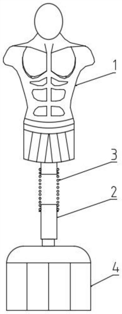
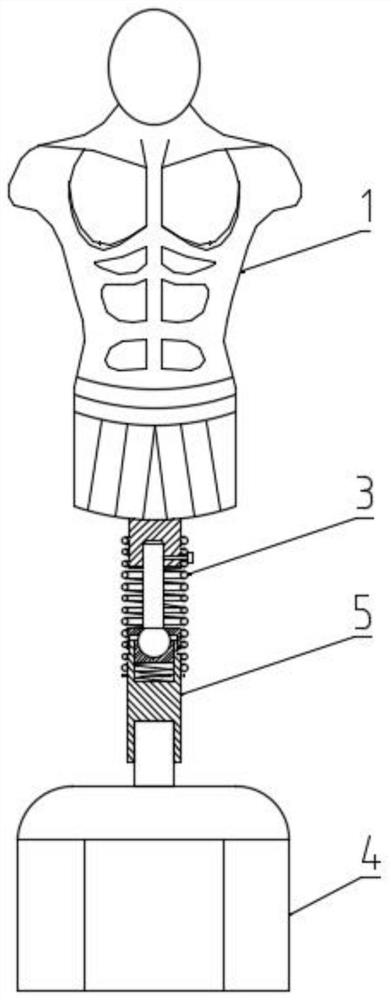
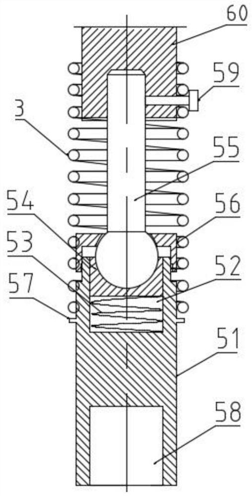
[0049] Such as Figure 2-3 As shown, a psychological pressure relief boxing receptor swinging part includes a venting part 1 and a base 4, and a joint-adjustable swinging device 5 is connected between the venting part 1 and the base 4; the joint-adjustable swinging device 5 includes a For the support rod 51 connected with the base 4, an installation cavity 52 is provided at the top of the support rod 51, a first compression spring 53 is arranged in the installation cavity 52, a slide seat 54 is provided on the upper end of the first compression spring 53, and a slide seat 54 is provided on the upper end of the slide seat 54. There is an arc groove; the ball at the lower end of the joint rod 55 is placed in the arc groove; the central hole of the adjustment cover 56 passes through the rod body of the joint rod 55 and is threadedly connected with the upper end of the support rod 51; the bottom end of the support rod 51 is arranged There is a mounting hole 58; the upper end of th...

Embodiment 2

[0051] Such as image 3 As shown, as a further optimization of the above embodiment: the outer wall of the upper end of the support rod 51 is provided with a limit ring 57 for supporting the swing spring 3 . The outer diameter of the limit ring 57 will be greater than the inner diameter of the swing spring 3, so that the limit ring 57 can hold the swing spring 3 and prevent the swing spring 3 from falling; Fix on the limit ring 57 .

Embodiment 3

[0053] Such as figure 2 As shown, as a further optimization of the above embodiment: the lower end of the drain part 1 is provided with a connecting shaft 60; the lower end of the connecting shaft 60 is provided with a connecting hole for connecting with the joint rod 55; the outer wall of the connecting shaft 60 is provided with a screw The screw hole is provided with a fixing screw 59 for fixing the joint rod 55 or / and the swing spring 3 . The connecting hole of connecting shaft 60 lower ends can be threaded hole, cooperates with the screw thread of joint bar 55 upper ends; The screw hole of connecting shaft 60 outer walls communicates connecting hole;


PUM


Abstract

The invention relates to the field of sporting goods and processing, in particular to a psychological pressure relief boxing receptor swing part and production and assembly equipment. It includes a vent part and a base, and a joint adjustable swing device is connected between the vent part and the base; the joint adjustable swing device includes a support rod for connecting with the base, and an installation cavity is provided on the top of the support rod, and a The first compression spring, the upper end of the first compression spring is provided with a sliding seat, and the upper end of the sliding seat is provided with an arc groove; the ball at the lower end of the joint rod is placed in the arc groove; the center hole of the adjustment cover passes through the rod body of the joint rod It is threadedly connected with the upper end of the support rod; the bottom end of the support rod is provided with a mounting hole; the upper end of the support rod is covered with a swing spring. The beneficial effects of the present invention are: the reset speed and the swing range of the joint rod can be controlled by rotating the adjustment cover, so that the swing range and swing speed of the catharsis person can be adjusted, which is suitable for different users.

Description

technical field [0001] The invention relates to the field of sporting goods and processing, in particular to a psychological pressure relief boxing receptor swing part and production and assembly equipment. Background technique [0002] Psychological pressure relief boxing receptor swing device is generally also called catharsis man, which is a dummy device commonly used in catharsis room to vent emotions, such as figure 1 As shown, it consists of a humanoid soft catharsis part 1 at the upper end, a base 4 at the lower end, and a support 2 connecting the receptor 1 and the base 4; the catharsis person hits the receptor to achieve catharsis and therapeutic effects. But present support member 2 is generally a rigid rod or is simply connected up and down by a spring. When a rigid rod is adopted, when the user hits and vents the person, the user itself will be subjected to a stronger rebound force, causing damage to the user. Injury, when it is simply connected by a spring, due...

Claims


Application Information

Patent Timeline
Patent Type & Authority Patents(China)
IPC IPC(8): A63B69/34
CPCA63B69/34
Inventor 戴娟毛先华孙移娇卢薇
Owner 岳阳职业技术学院
Why Eureka
Try Eureka