Puncture biopsy equipment for preoperative pathological diagnosis of liver cancer
A technology for pathological diagnosis and puncture biopsy, applied in the directions of inoculation and ovulation diagnosis, diagnosis, puncture needle, etc., can solve the problem of easy deviation of puncture biopsy, and achieve the effect of accurate puncture position and easy inspection.
- Summary
- Abstract
- Description
- Claims
- Application Information
AI Technical Summary
Problems solved by technology
Method used
Image
Examples
Embodiment 1
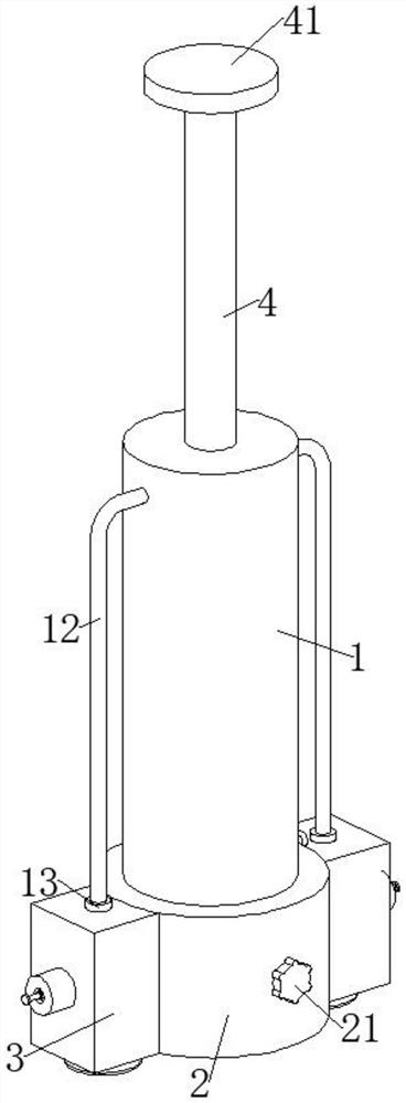
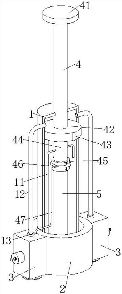
[0027] The present invention provides a technical solution: a puncture biopsy device for preoperative pathological diagnosis of liver cancer, including an installation cylinder 1, a piston plate 42 is slidably connected to the installation cylinder 1, a slider 43 is fixedly connected to the piston plate 42, and the installation cylinder 1 There is a chute 11 that cooperates with the slider 43, the piston plate 42 fits the inner wall of the installation cylinder 1, the upper surface of the piston plate 42 is fixedly connected with the push rod 4, and the installation cylinder 1 is provided with a chute that cooperates with the push rod 4. The top of the push rod 4 is fixedly connected with a push plate 41, the lower surface of the piston plate 42 is fixedly connected with a first cylinder 44, and the bottom of the first cylinder 44 is coaxially fixedly connected with a second cylinder 45. A puncture needle 5 is installed on the barrel 45, a cylinder 2 is slidably connected to th...
Embodiment 2
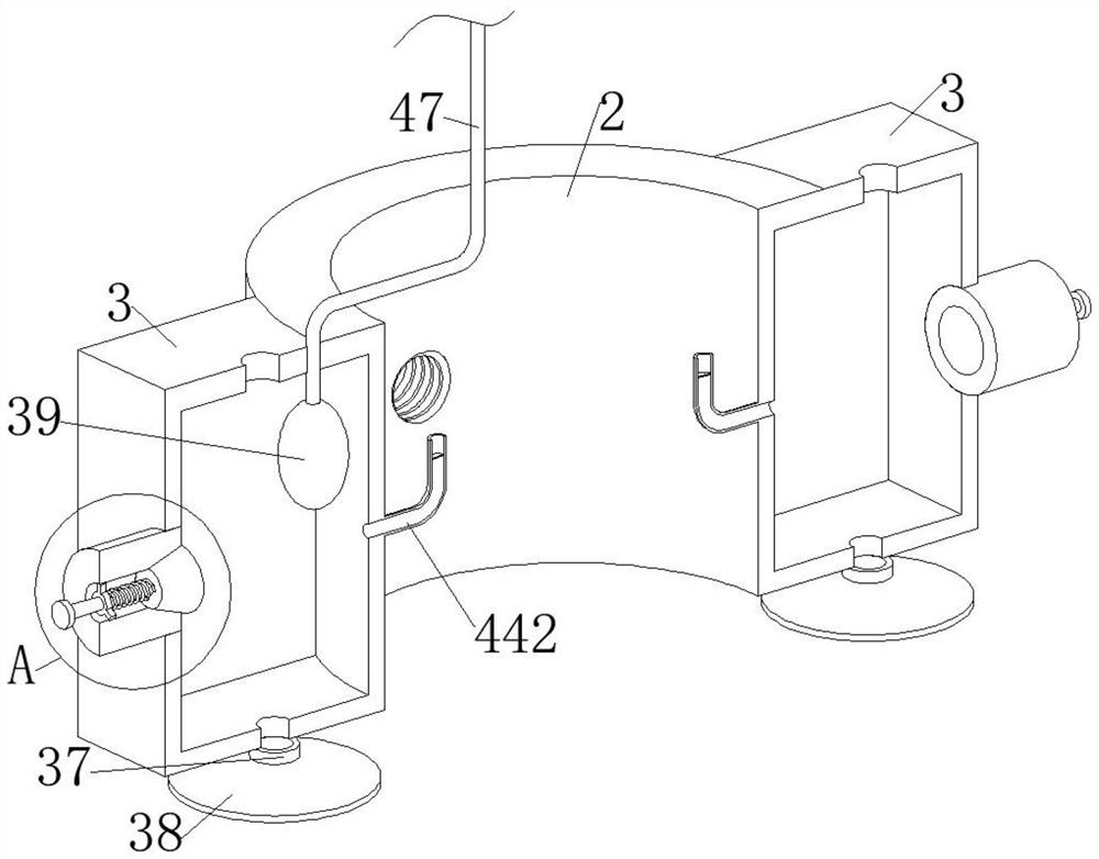
[0032] Further on the basis of Embodiment 1, the outer diameter of the puncture needle 5 is equal to the inner diameter of the second cylindrical body 45, the second cylindrical body 45 is fixedly connected with an annular air bag 46, and the second cylindrical body 45 is slidably connected with a U-shaped positioning rod 48, the two ends of U-shaped positioning rod 48 are all offset against puncture needle 5 intermittently, two limit plates 49 are symmetrically fixedly connected on U-shaped positioning rod 48, and U-shaped positioning rod 48 is positioned at puncture needle 5 and puncture needle 5. A second tension spring 491 is sleeved on the horizontal section between the two limiting plates 49, and both ends of the two second tension springs 491 are fixedly connected to the second cylinder 45 and the corresponding limiting plate 49, The annular airbag 46 and the U-shaped positioning rod 48 offset intermittently, the negative pressure box 3 is fixedly connected with a spheri...
Embodiment 3
[0035] Further on the basis of the second embodiment, the first cylinder 44 is fixedly connected with a first L-shaped pipe 441, the negative pressure box 3 is fixedly connected with a second L-shaped pipe 442, and the installation cylinder 1 is provided with a The through groove that the second L-shaped pipe 442 cooperates, the inner diameter of the second L-shaped pipe 442 is equal to the inner diameter of the first L-shaped pipe 441, the second L-shaped pipe 442 is fixedly connected with a plastic sheet 443, the first L-shaped pipe 441 An annular thorn 444 for piercing the plastic sheet 443 is fixedly connected to the top.
[0036] refer to figure 2 , image 3 , Figure 5 with Figure 8 , when the pushing force is continuously applied to the push plate 41, the first cylindrical body 44 will get closer and closer to the negative pressure box 3, and then the first L-shaped tube 441 fixedly connected to the first cylindrical body 44 will also get closer and closer The sec...
PUM
 Abstract
Description
Claims
Application Information
 - R&D
- Intellectual Property
- Life Sciences
- Materials
- Tech Scout
- Unparalleled Data Quality
- Higher Quality Content
- 60% Fewer Hallucinations
Browse by: Latest US Patents, China's latest patents, Technical Efficacy Thesaurus, Application Domain, Technology Topic, Popular Technical Reports.
© 2025 PatSnap. All rights reserved.Legal|Privacy policy|Modern Slavery Act Transparency Statement|Sitemap|About US| Contact US: help@patsnap.com


