
Multi-feature fusion visual positioning method based on inverse projection

A multi-feature fusion, visual positioning technology, applied in the field of visual positioning and visual measurement, can solve the problem of low accuracy

Active Publication Date: 2021-12-21
中国人民解放军63920部队
View PDF7 Cites 0 Cited by
  • Summary
  • Abstract
  • Description
  • Claims
  • Application Information

AI Technical Summary

Problems solved by technology

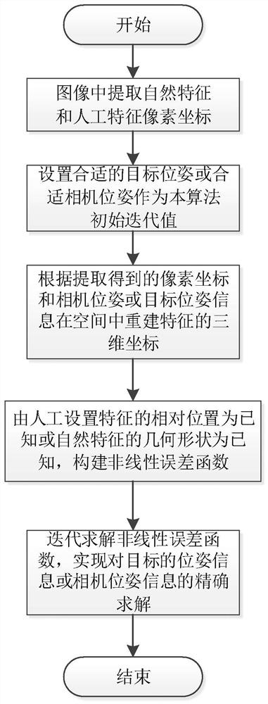
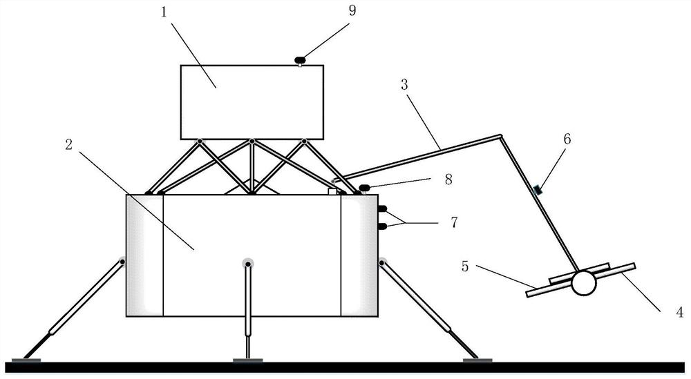
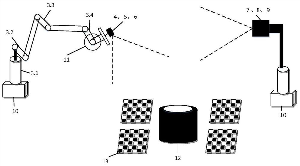
[0006] Aiming at the problems of low accuracy of vision-guided operations in the operations of sampling, setting out, grabbing and releasing cans by the robotic arm in the sampling task of extraterrestrial celestial bodies, and the problems that a unified optimization model has not been established to solve them, the present invention proposes a multi- The feature fusion visual positioning method, through the abstract modeling of the process of static camera measurement of dynamic targets and dynamic camera measurement of static targets, establishes binocular and monocular cameras for natural features (such as circular targets) and artificially set features (such as target feature) combination positioning optimization model, which realizes the combination positioning of multiple types of features suitable for different camera numbers in different operation application scenarios, and effectively improves the use of robotic arms to collect samples, place samples, grab sealed cans and place them in the remote operation of extraterrestrial celestial bodies. Operation accuracy and automation of key links such as sealed tanks

Method used


Image

  • Multi-feature fusion visual positioning method based on inverse projection
  • Multi-feature fusion visual positioning method based on inverse projection
  • Multi-feature fusion visual positioning method based on inverse projection

Examples


Embodiment Construction

[0044] In order to enable those skilled in the art to better understand the solution of the present application, the technical solution in the embodiment of the application will be clearly and completely described below in conjunction with the accompanying drawings in the embodiment of the application. Obviously, the described embodiment is only It is an embodiment of a part of the application, but not all of the embodiments. Based on the embodiments in this application, all other embodiments obtained by persons of ordinary skill in the art without creative efforts shall fall within the scope of protection of this application.

[0045] Those skilled in the art should understand that the embodiments of the present invention may be provided as methods, systems, or computer program products. Accordingly, the present invention can take the form of an entirely hardware embodiment, an entirely software embodiment, or an embodiment combining software and hardware aspects.

[0046] I...


PUM


Abstract

The invention discloses a multi-feature fusion visual positioning method based on inverse projection. The method comprises the following steps: 1) extracting feature pixel coordinates formed by forward projection of a space target in a camera image; 2) determining N cameras in the space, wherein N1 cameras are static cameras; n2 cameras are dynamic cameras; setting an appropriate camera pose or a space target pose as an algorithm initial iteration value according to whether the camera pose is a fixed parameter or not; 3) reconstructing the three-dimensional coordinates of the features in the space according to the known camera pose information or target pose information and the pixel coordinates of the target features; (4) according to the reconstructed space coordinates, creating a unified pose optimization model of relative measurement of the camera on the multiple types of features by utilizing known fixed constraints between the features; and 5) iteratively solving the pose measurement optimization model by using a nonlinear optimization method, and obtaining the precise pose information of the space target or the mechanical arm-mounted camera, so that the mechanical arm is gradually and precisely guided and controlled, and a predetermined working program and task are executed.

Description

technical field [0001] The invention relates to the technical fields of visual measurement and visual positioning, in particular to a multi-feature fusion visual positioning method based on back projection. Background technique [0002] With the development of science and technology, the mechanical arm is not only more and more widely used on the ground, but also plays an increasingly important role in the landing detection of the surface of extraterrestrial celestial bodies, especially for the sampling operation of the surface of extraterrestrial celestial bodies. . [0003] Landing sampling and return on the surface of extraterrestrial celestial bodies is an important means for the world's aerospace powers to explore deep space and expand human understanding of alien planets and the solar system. The robotic arm is an essential key equipment for landing sampling tasks on the surface of extraterrestrial celestial bodies. It can independently perform sampling tasks accordin...

Claims


Application Information

Patent Timeline
Patent Type & Authority Applications(China)
IPC IPC(8): G06T7/73G06T5/00G06K9/46G06K9/62
CPCG06T7/73G06T2207/10004G06T2207/20221G06F18/253G06T5/80
Inventor 刘传凯李东升谢剑锋王俊魁袁春强张济韬刘茜王晓雪何锡明胡晓东
Owner 中国人民解放军63920部队
Learn More