Testing equipment and testing method for wind-induced vibration and galloping performance of optical cable

A technology for testing equipment and testing methods, which is applied in the direction of measuring devices, instruments, etc., and can solve the problems that ADSS optical cables and OPGW optical cables cannot reflect the stress of ADSS optical cables or OPGW optical cables.

Pending Publication Date: 2021-12-21
TONGDING INTERCONNECTION INFORMATION CO LTD
View PDF0 Cites 1 Cited by
  • Summary
  • Abstract
  • Description
  • Claims
  • Application Information

AI Technical Summary

Problems solved by technology

[0005] The technical problem to be solved by the present invention is: in order to solve the problem that the test results of ADSS optical cable and OPGW optical cable in the prior art cannot reflect the actual stress situation of ADSS optical cable or OPGW optical cable under the action of wind force in actual use, thereby providing an optical cable Test equipment and test methods for wind-induced vibration and galloping performance

Method used


Image

  • Testing equipment and testing method for wind-induced vibration and galloping performance of optical cable
  • Testing equipment and testing method for wind-induced vibration and galloping performance of optical cable

Examples


Embodiment

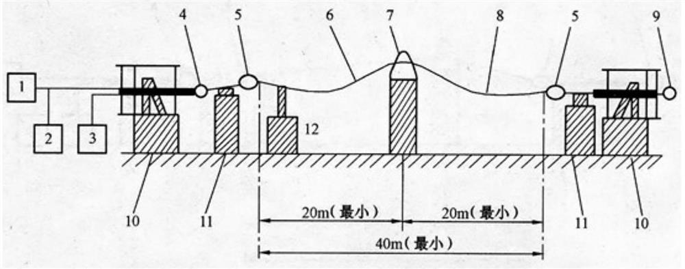
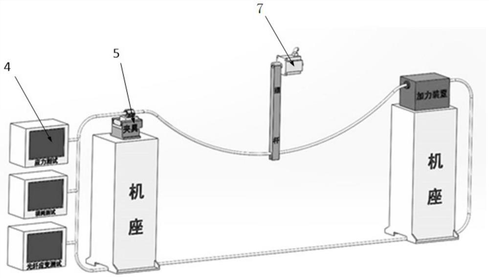
[0052] This embodiment provides a kind of test equipment for wind-induced vibration and galloping performance of optical cable, such as figure 1 , 2 shown, including:

[0053] There are two terminal supports 10, which are arranged at both ends of the test equipment;

[0054] An optical fiber connector 9 is mounted on one of the terminal supports 10 for fixing one end of the optical cable to be tested;

[0055] The force measuring mechanism 4 is installed on the other terminal support 10, and is used to measure the tensile force of the end of the optical cable to be tested;

[0056] Optical fiber dispersion test system, used to connect to the end of the optical cable to measure the change of fiber length and attenuation at the typical wavelength of the optical transmission window;

[0057] The suspension device 7 is arranged in the middle of the two terminal supports 10, and is used for arbitrarily swinging the middle position of the optical cable to be tested;

[0058] The...


PUM

PropertyMeasurementUnit
lengthaaaaaaaaaa
lengthaaaaaaaaaa
diameteraaaaaaaaaa

Abstract

The invention relates to testing equipment for wind-induced vibration and galloping performance of an optical cable, and the equipment comprises terminal supports which are disposed at two ends of the test equipment; an optical fiber connector which is used for fixing one end of a to-be-tested optical cable; a force measuring mechanism which is used for measuring the tensile force of the end part of the to-be-measured optical cable; an optical fiber dispersion test system which is used for being connected to the end part of the to-be-tested optical cable so as to measure the change conditions of the optical fiber length and attenuation under the typical wavelength of the optical transmission window; a suspension device which is used for supporting the middle position of the to-be-tested optical cable; a middle support which is used for supporting the two ends of the to-be-tested optical cable; a vibration exciter which is used for exciting the to-be-measured optical cable on a vertical plane; and a terminal device which is used for clamping the optical cable. An electronic vibration exciter is adopted to excite the optical cable on a vertical plane, and the fatigue performance of the optical cable and the optical performance change of optical fibers in the optical cable are simulated and determined under the vibration condition that the actual operation stress state of the optical cable is different.

Description

technical field [0001] The application belongs to the technical field of optical cable testing, and in particular relates to a test device and test method for wind-induced vibration and galloping performance of optical cable. Background technique [0002] ADSS optical cable, All-dielectric Self-supporting Optical Cable (also known as all-dielectric self-supporting optical cable). All-dielectric means that the optical cable uses all-dielectric materials. Self-supporting means that the strengthening member of the optical cable itself can bear its own weight and external load. [0003] OPGW optical cable, Optical Fiber Composite Overhead Ground Wire (also known as optical fiber composite overhead ground wire). The optical fiber is placed in the ground wire of the overhead high-voltage transmission line to form an optical fiber communication network on the transmission line. This structure has dual functions of ground wire and communication, and is generally called OPGW optical...

Claims


Application Information

Patent Timeline
Patent Type & Authority Applications(China)
IPC IPC(8): G01D21/02
CPCG01D21/02
Inventor 沈小平肖仁贵周道胡震杰陈斌沈林林张洋丁晓莉沈东妹
Owner TONGDING INTERCONNECTION INFORMATION CO LTD
Why Eureka
Try Eureka