Splicing type bed system of high-rigidity gantry machining center
A high-rigidity, splicing technology, applied in the direction of metal processing equipment, metal processing machinery parts, manufacturing tools, etc., can solve the problems of poor rigidity of the bed, difficulty in ensuring the coplanarity of the guide rail surface of the spliced bed, etc. Achieve the effect of improving rigidity and stability, facilitating casting and transportation, and maintaining long-term stability
- Summary
- Abstract
- Description
- Claims
- Application Information
AI Technical Summary
Problems solved by technology
Method used
Image
Examples
Embodiment 1
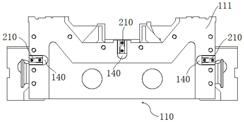
[0047] combine Figure 1-Figure 7 , a spliced bed system of a high-rigidity gantry machining center in this embodiment includes a common bed 110 and a spliced bed 120, wherein the common bed 110 can adopt a uniform size, and the spliced bed 120 can adopt different lengths and sizes , using the common bed 110 of the same size and the splicing bed 120 of different sizes can splice the required different lengths of the gantry machining center bed, realize the splicing and use of different length machine tools, reduce the length of the single bed, and benefit Casting and transportation; at the same time, the common bed is used as a common material, which is conducive to stocking and reducing production costs. In this embodiment, the common bed 110 and the splicing bed 120 are connected by connecting screws. Specifically, the joint surfaces of the common bed 110 and the splicing bed 120 in this embodiment are the public installation surface 111 and the splicing surface respec...
Embodiment 2
[0058] A spliced bed system of a high-rigidity gantry machining center in this embodiment has a basic structure as in Embodiment 1. Furthermore, in this embodiment, a sealing groove 122 is provided on the splicing mounting surface 121, and a sealing groove 122 is arranged in the sealing groove 122. The sealing ring can effectively improve the sealing performance of the joint surface, ensure the stability of the joint surface at the splicing joint, and further provide guarantee for the subsequent processing accuracy.
[0059] Such as figure 2 As shown, in this embodiment, both sides of the common bed 110 and the spliced bed 120 in the width direction near the joint are provided with oil retaining grooves 130, and the oil retaining grooves 130 can guide the lubricating oil on the line rails to the bed. It can not only effectively prevent oil and water from penetrating into the joint surface and affect the stability of the joint surface, but also prevent oil and water from p...
Embodiment 3
[0064] The spliced bed system of a high-rigidity gantry machining center in this embodiment has a basic structure as in Embodiment 2. Furthermore, in this embodiment, a plurality of sheet metal plates are arranged on the side wall of the base near the guide rail 300 in the collecting tank 350 The joint surface 360, the sheet metal joint surface 360 is used to connect with the metal protective shell, can wrap the guide rail 300 inside, change the sheet metal joint surface 300 at the bottom of the guide rail 300 to the inside, prevent water seepage and leakage, and improve the water resistance of the machine tool. Improve the user's working surface cleanliness.
[0065] In this embodiment, the bottom of the common bed 110 is provided with a plurality of anchor bolts 103, and the plurality of anchor bolts 103 is more convenient for horizontal adjustment and more stable for support.
[0066] In this embodiment, the side of the bottom of the column support 310 close to the guid...
PUM
 Abstract
Description
Claims
Application Information
 - R&D
- Intellectual Property
- Life Sciences
- Materials
- Tech Scout
- Unparalleled Data Quality
- Higher Quality Content
- 60% Fewer Hallucinations
Browse by: Latest US Patents, China's latest patents, Technical Efficacy Thesaurus, Application Domain, Technology Topic, Popular Technical Reports.
© 2025 PatSnap. All rights reserved.Legal|Privacy policy|Modern Slavery Act Transparency Statement|Sitemap|About US| Contact US: help@patsnap.com


