
Automatic high-efficiency gluing equipment for electronic components

A technology for electronic components and gluing, which is applied to coatings, devices that apply liquid to surfaces, etc. It can solve the problems of low spraying efficiency, small spraying range, and no lifting and rotating functions, so as to improve spraying efficiency. , speed up the efficiency, improve the effect of spraying range

Pending Publication Date: 2021-12-21
湖南芷江正向科技有限公司
View PDF10 Cites 0 Cited by
  • Summary
  • Abstract
  • Description
  • Claims
  • Application Information

AI Technical Summary

Problems solved by technology

[0005] The main purpose of the present invention is to provide an automatic electronic component high-efficiency gluing equipment, which can effectively solve the lack of fixing of electronic components in the background technology. The effect of the glue does not have the function of lifting and rotating, and the spraying position of the glue cannot be controlled according to the electronic components. The spraying range is relatively small and the spraying efficiency is low.

Method used


Image

  • Automatic high-efficiency gluing equipment for electronic components
  • Automatic high-efficiency gluing equipment for electronic components
  • Automatic high-efficiency gluing equipment for electronic components

Examples


Embodiment Construction

[0032] In order to make the technical means, creative features, goals and effects achieved by the present invention easy to understand, the present invention will be further described below in conjunction with specific embodiments.

[0033] In the description of the present invention, it should be noted that the terms "upper", "lower", "inner", "outer", "front end", "rear end", "both ends", "one end", "another end" The orientation or positional relationship indicated by etc. is based on the orientation or positional relationship shown in the drawings, and is only for the convenience of describing the present invention and simplifying the description, rather than indicating or implying that the referred device or element must have a specific orientation, use a specific Azimuth configuration and operation, therefore, should not be construed as limiting the invention. In addition, the terms "first" and "second" are used for descriptive purposes only, and should not be understood ...


PUM


Abstract

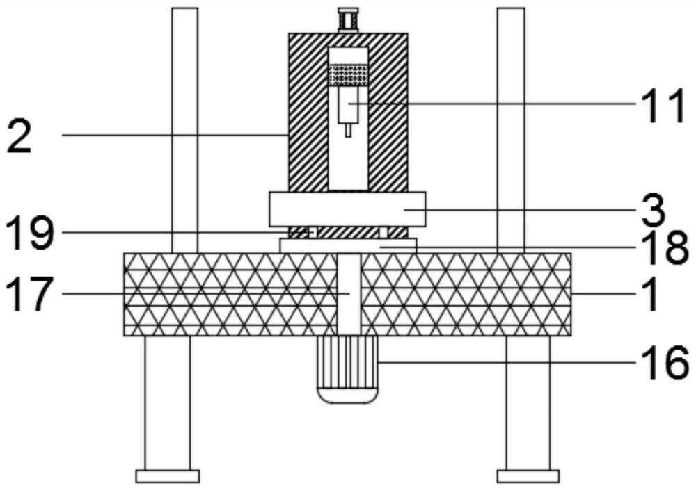
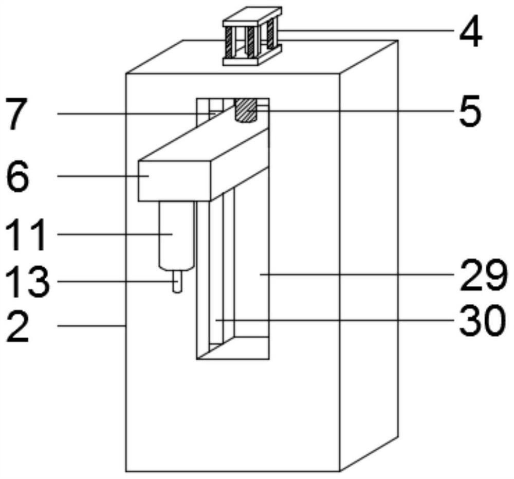
The invention discloses automatic high-efficiency gluing equipment for electronic components, and relates to the technical field of electronic component gluing equipment. The automatic high-efficiency gluing equipment comprises a machining table, a control box and a containing plate arranged on the machining table, wherein a first air cylinder is arranged at the top of the control box; the control box is connected with a lifting mechanism through the first air cylinder; the bottom of the lifting mechanism is connected with a fine adjustment mechanism; a gluing mechanism is arranged above the containing plate; a fixing mechanism is arranged in the containing plate; the lifting mechanism comprises a connecting rod, a moving block and a sliding block; the fine adjustment mechanism comprises an electric sliding rail, a vehicle body and a fixing frame; and the fixing mechanism comprises a second air cylinder, a damping frame, a movable column, a limiting plate, a damping spring and a clamping plate. According to the automatic high-efficiency gluing equipment for the electronic components, the height of a spraying mechanism can be adjusted, the electronic components can be firmly fixed, the spraying range is widened, the spraying effect is improved, the spraying efficiency is improved, full-automatic spraying is achieved, manual operation is not needed, convenience and rapidness are achieved, and manpower and material resources are saved.

Description

technical field [0001] The invention relates to the technical field of gluing equipment for electronic components, in particular to an automatic high-efficiency gluing equipment for electronic components. Background technique [0002] Electronic components are components of electronic components and small machines and instruments. They are often composed of several parts and can be used in similar products; they often refer to certain parts in industries such as electrical appliances, radios, and instruments. They are capacitors, transistors, The general term for electronic devices such as hairsprings and springs; common ones include diodes, etc. With the development of the times, the history of electronic components is actually a condensed history of electronic development. Electronic technology is an emerging technology developed at the end of the nineteenth century and the beginning of the twentieth century. It developed the fastest and was the most widely used in the twe...

Claims


Application Information

Patent Timeline
Patent Type & Authority Applications(China)
IPC IPC(8): B05C5/02B05C11/10B05C13/02
CPCB05C5/0208B05C11/1002B05C13/02
Inventor 王峰宗留杨杨新民张亚男
Owner 湖南芷江正向科技有限公司
Learn More