
Large-aperture transmission-type medium-wave refrigeration infrared continuous zooming thermal imager

A transmission-type, large-aperture technology, applied in the field of infrared thermal imaging, can solve the problems of energy loss in the central area, low energy detection capability, and difficult installation and adjustment, so as to reduce the length and volume of the system and ensure the consistency of the optical axis. , The effect of small processing and adjustment difficulty

Active Publication Date: 2021-12-17
西安中科立德红外科技有限公司
View PDF4 Cites 0 Cited by
  • Summary
  • Abstract
  • Description
  • Claims
  • Application Information

AI Technical Summary

Problems solved by technology

[0004] The purpose of the present invention is to solve the problems in the existing continuous zoom infrared thermal imaging system that the size of the catadioptric system is large, the installation and adjustment are difficult, the energy loss in the central area is serious, and the transmission system with a small aperture has a small aperture and low energy detection capability. , the technical problem of relatively short working distance, providing a large-aperture transmission type mid-wave cooling infrared continuous zoom thermal imager

Method used


Image

  • Large-aperture transmission-type medium-wave refrigeration infrared continuous zooming thermal imager
  • Large-aperture transmission-type medium-wave refrigeration infrared continuous zooming thermal imager
  • Large-aperture transmission-type medium-wave refrigeration infrared continuous zooming thermal imager

Examples


Embodiment Construction

[0049] The present invention will be further described below in conjunction with the accompanying drawings and embodiments.

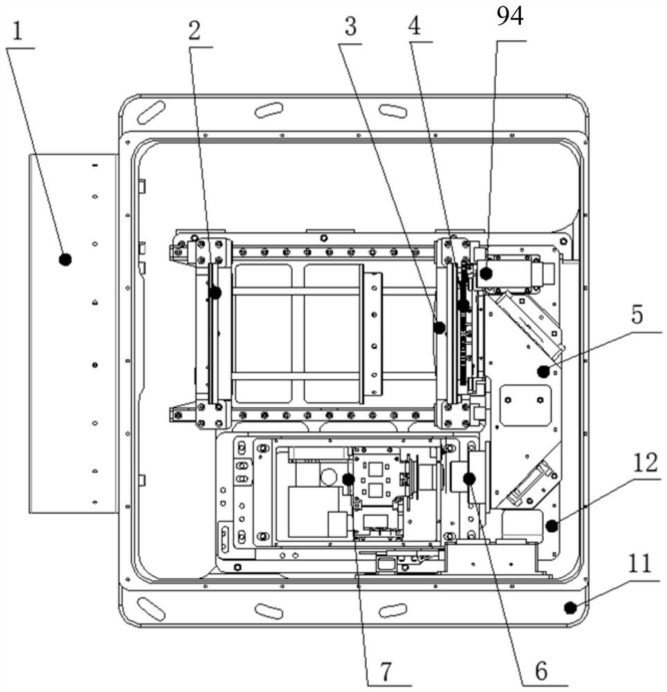
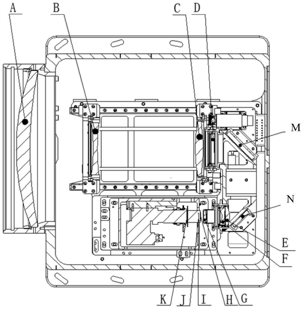
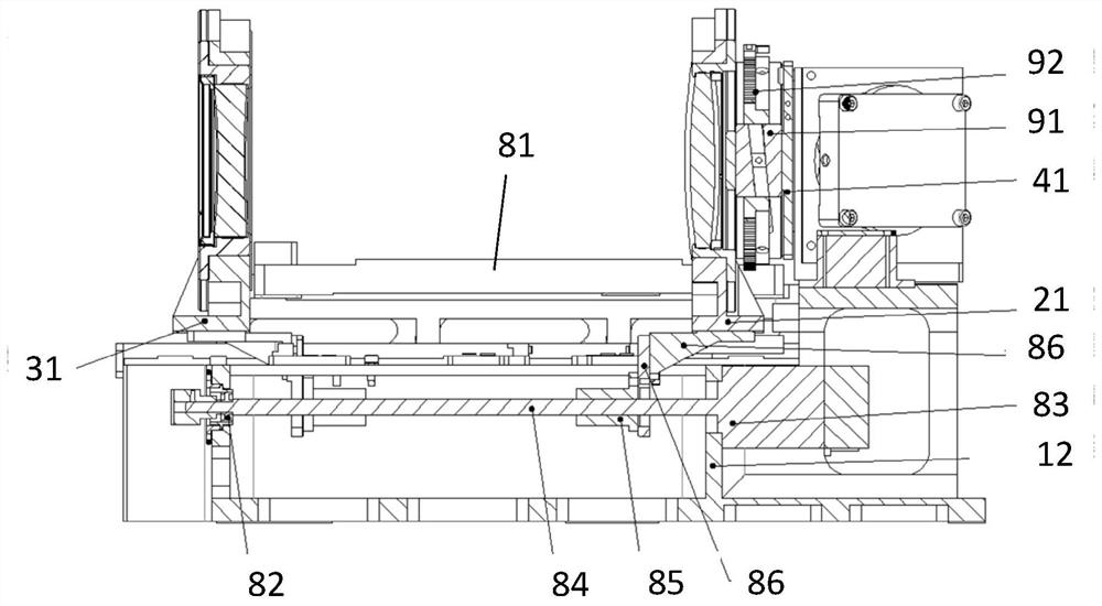
[0050]The large-diameter transmission type medium-wave cooling infrared continuous zoom thermal imager of the present invention includes a housing 11, a bracket 12 and a drive unit arranged in the housing 11, a front fixing group 1 fixedly connected to the front end of the housing 11, a set The external interface on the housing 11, the zoom group 2 installed through the bracket 12, the compensation group 3, the focus group 4, the reflection group 5, the relay group 6, the detector protection window H, the filter I, Cold rail J and core set 7; the core set 7 includes detectors and circuit board components for completing imaging, image processing, image output and drive unit control, that is, the core set 7 is mainly used to realize photoelectric signal conversion , convert the optical signal into an image, and perform image processing and image output; t...


PUM


Abstract

The invention relates to a large-aperture transmission-type medium-wave refrigeration infrared continuous zooming thermal imager, and aims to solve the technical problems that in an existing continuous zooming infrared thermal imaging system, a catadioptric system is large in size and large in installation and adjustment difficulty, the energy loss of a central area is serious, and a small-aperture transmission-type system is small in clear aperture, low in energy detection capability, and relatively short in acting distance. The thermal imager comprises a driving unit, a shell, a bracket arranged in the shell, a front fixing group fixedly connected to the front end surface of the shell, an external interface arranged on the shell, and a zoom group, a compensation group, a focusing group, a reflection group, a relay group, a detector protection window H, an optical filter I, a cold diaphragm J and a movement group which are mounted through the bracket, a reflector group comprises two reflectors which are perpendicular to each other to form a U-shaped light path, and the light path is turned by 180 degrees; and the driving unit is used for driving the zoom group, the compensation group and the focusing group to move along the optical axis.

Description

technical field [0001] The invention relates to infrared thermal imaging technology, in particular to a large-diameter transmission type medium-wave cooling infrared continuous zoom thermal imager, which can be mounted on theodolite, turntable and other equipment, and is mainly used for searching, tracking and measuring. Background technique [0002] In recent years, continuous zoom infrared thermal imaging systems have been widely used in many aspects, and related technologies have developed rapidly. The continuous zoom thermal imager can realize large field of view search and small field of view tracking. The imaging effect is good during the zooming process without losing the target. It has the needs and effects that fixed-focus thermal imagers and multi-field thermal imagers cannot meet. [0003] The longer detection distance, higher detection sensitivity, higher resolution and longer working distance generally required by infrared thermal imaging cameras put forward hig...

Claims


Application Information

Patent Timeline
Patent Type & Authority Applications(China)
IPC IPC(8): G02B15/15G02B7/04
CPCG02B15/15G02B7/04Y02A90/10
Inventor 刘伟焦洋洋郭得福闫福文段程鹏
Owner 西安中科立德红外科技有限公司
Learn More