
Optical transmitting assembly and optical transceiver module

A technology for optical transmitting components and optical transceiver modules, applied in the field of optical communication, can solve the problem that the optical power value of the transmitting end cannot meet the requirements, etc., and achieve the effect of improving the imbalance of multi-path light and improving the coupling efficiency.

Pending Publication Date: 2021-12-17
GUANGXUN SCI & TECH WUHAN
View PDF0 Cites 2 Cited by
  • Summary
  • Abstract
  • Description
  • Claims
  • Application Information

AI Technical Summary

Problems solved by technology

[0003] The purpose of the present invention is to provide a light emitting component and an optical transceiver module to solve the technical problem that the optical power value of the transmitting end of the light transmitting component in the prior art cannot meet the requirements

Method used


Image

  • Optical transmitting assembly and optical transceiver module
  • Optical transmitting assembly and optical transceiver module
  • Optical transmitting assembly and optical transceiver module

Examples


Embodiment Construction

[0033] Specific embodiments of the present disclosure will be described in further detail below in conjunction with the accompanying drawings and. "First," "second," and the like described in the present invention, for illustrative purposes only, and not intended to indicate or imply relative importance or technical features specified implicitly indicated by the number or order. Thereby, the features of "first", "second" may be defined, and at least one of the features may be indicated or implied. In the description of the invention, the meaning of "plurality" is at least two, such as two, three, etc., unless otherwise specifically defined.

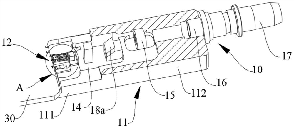
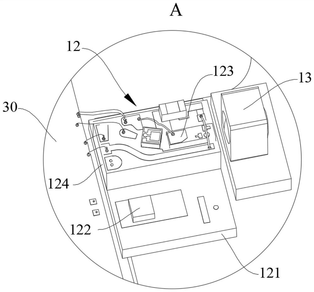
[0034] Refer Figure 1 to 4 , A first aspect of the embodiment of the present application, there is provided a light emitting assembly including a first substrate 11 and are sequentially disposed on the first substrate 11 of the laser assembly 12 collimator lens 13 is incident, the light path adjusting member 14, the outgoing registration the ...


PUM


Abstract

The invention provides an optical transmitting assembly and an optical transceiver module. The optical transmitting assembly comprises a first substrate, and a laser assembly, an incident collimating lens, an optical path adjusting member, an emergent collimating lens and an optical fiber assembly which are sequentially arranged on the first substrate; a light beam emitted by the laser assembly is converted into collimated light through the incident collimating lens; and the optical path adjusting member is arranged between the incident collimating lens and the emergent collimating lens so as to correct the light path deviation of the optical transmitting assembly after the positions of the laser assembly, the emergent collimating lens and the optical fiber assembly are fixed, so that the collimated light output from the optical path adjusting member is coupled into the optical fiber assembly after passing through the emergent collimating lens. In the optical transmitting assembly, after other light components in the light path are mounted, light beam deviation caused by mounting deviation of each light component and raw material processing error can be adjusted by adjusting the light path adjusting piece, so that the coupling efficiency of light in the light path is improved; and further the optical power value of the transmitting end of the optical transmitting assembly meets the requirements of the optical transceiver module.

Description

Technical field [0001] The present invention relates to the field of optical communication technology, particularly relates to an optical transceiver module and a light emitting assembly. Background technique [0002] With the development of optical communication technology, the data center of the light module and the single wave 100Gbps module 4 * 100Gbps development of a 4 * 25Gbps module to 100G. Currently 400G module, the laser module is widely used in chip EML, the luminous power is not high, but the optical transceiver module of its optical power value of the transmitting end of the range have strict requirements, which requires high as possible module 400G optical power value which the transmitting end. Inventive content [0003] Object of the present invention is to provide an optical transceiver module and a light emitting assembly, to solve the technical problems of the prior art optical power of the transmitting end of the light emitting assembly can not meet the requ...

Claims


Application Information

Patent Timeline
IPC IPC(8): G02B6/42
CPCG02B6/4206G02B6/4225
Inventor 马洪勇苏敬奎宋耕胡毅罗勇孙莉萍
Owner GUANGXUN SCI & TECH WUHAN
Learn More