
Heat dissipation demisting system for automobile lamp parts

A technology of parts and lamps, which is applied in the field of heat dissipation and defogging systems, can solve the problems of affecting the driving safety of the driver's sight, the increase of the cost of the whole lamp, and the occupation of space, so as to eliminate the condensation phenomenon, reduce the cost of the whole lamp, and speed up the flow Effect

Pending Publication Date: 2021-12-17
MAGNETI MARELLI AUTOMOTIVE COMPONENTS WUHU
View PDF0 Cites 0 Cited by
  • Summary
  • Abstract
  • Description
  • Claims
  • Application Information

AI Technical Summary

Problems solved by technology

When the various light sources in the lamp are turned on, the internal heating components generate heat to increase the temperature of the air inside the lamp. When the hot air contacts the relatively low temperature environment outside the outer cover, the temperature will drop and precipitate water vapor to condense on the inner wall of the outer cover to form fog, making the car The light emitted by the light source produces irregular refraction, which affects the light shape and brightness of the entire car light, which in turn affects the driver's sight and driving safety
[0003] Existing car lights usually use enlarged radiators, fans or multiple ventilation holes to increase the air circulation in the lamp to help the system in the lamp dissipate heat and eliminate condensed fog, resulting in an increase in the cost of the entire lamp and taking up a lot of space in the car , resulting in difficulties in the internal space arrangement of the lights

Method used


Image

  • Heat dissipation demisting system for automobile lamp parts
  • Heat dissipation demisting system for automobile lamp parts
  • Heat dissipation demisting system for automobile lamp parts

Examples


Embodiment Construction

[0023] In order to deepen the understanding of the present invention, the present invention will be further described below in conjunction with examples, which are only used to explain the present invention and do not constitute a limitation to the protection scope of the present invention.

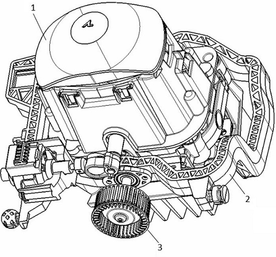
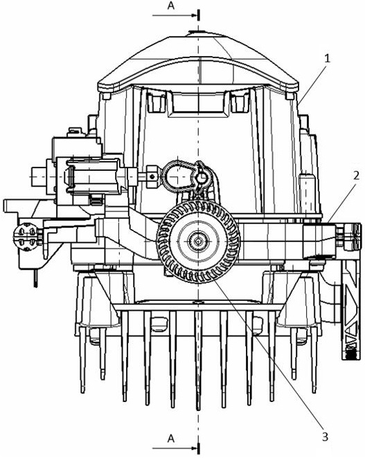
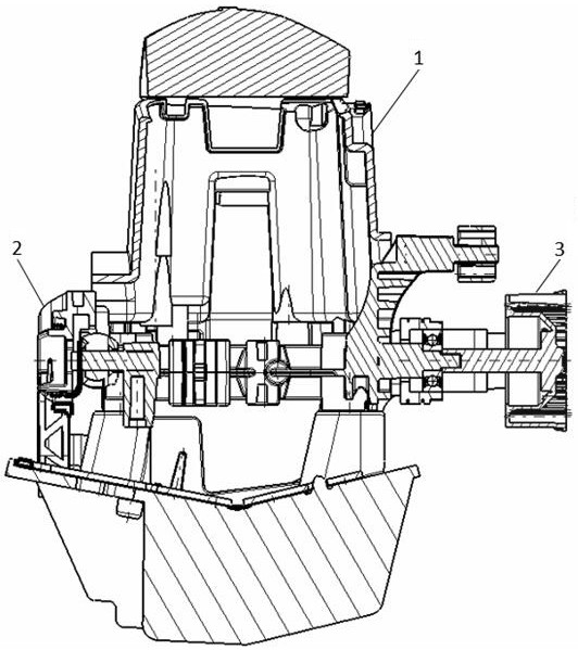
[0024] Such as Figure 1-6 As shown, this embodiment is a heat dissipation and defogging system for automotive lamp components, including an optical module 1 , a module bracket 2 , and an impeller 3 . The optical module is installed on the module bracket through a pair of rotating shafts, and the impeller is installed on the rotating shaft of the optical module through interference fit or welding.

[0025] In this embodiment, the optical module 1 is provided with an upper rotary shaft 11 and a lower rotary shaft 12 . The module bracket 2 is provided with two shaft holes 21 . The impeller 3 is provided with a rotating shaft 31 and a mounting hole 32 .

[0026] The car light system has a...


PUM


Abstract

The invention provides a heat dissipation and demisting system for automobile lamp parts. The heat dissipation and demisting system comprises an optical module, a module support and an impeller. An upper rotating shaft and a lower rotating shaft are arranged on the optical module; the module support is provided with two rotating shaft holes; a rotating shaft is arranged on the impeller, and a mounting hole is formed in the middle of the rotating shaft; the upper rotating shaft and the lower rotating shaft are correspondingly mounted in the two rotating shaft holes, and the mounting hole of the rotating shaft is mounted on one rotating shaft in an interference fit manner; the optical module has a follow-up steering function and rotates around the rotating shaft according to the change of the deflection direction of the vehicle in real time according to the external power of the control signal, the light direction is consistent with the driving direction of the vehicle, and after the vehicle starts driving, the follow-up steering function enables the rotating shaft of the optical module to be in a rotating motion state at high frequency; and the impeller is driven to be in a high-frequency rotating motion state, air flow in the lamp is greatly promoted, and the heat dissipation and demisting functions are achieved.

Description

technical field [0001] The invention relates to the field of automobile lighting, in particular to a heat dissipation and defogging system for automobile lamp parts. Background technique [0002] With the development of automobile industry technology and the changing trend of automobile styling design, the functions of car lights are becoming more and more complex and changeable. There are more and more heating components in the lamp, and the temperature inside the lamp is also getting higher and higher. At the same time, the miniaturization of car lights has also become a trend in the development of car lights. The space inside the lights is becoming more and more tight, making air circulation more difficult. When the various light sources in the lamp are turned on, the internal heating components generate heat to increase the temperature of the air inside the lamp. When the hot air contacts the relatively low temperature environment outside the outer cover, the temperature...

Claims


Application Information

Patent Timeline
IPC IPC(8): F21S45/43F21S45/60F21W107/10
CPCF21S45/43F21S45/60F21W2107/10
Inventor 李继友
Owner MAGNETI MARELLI AUTOMOTIVE COMPONENTS WUHU
Learn More