
Wind-solar complementary solar street lamp

A solar street light, wind-solar complementary technology, applied in the field of street lights, can solve the problem of photovoltaic panels affecting the stability of street lights, etc., and achieve the effect of reducing wind resistance

Inactive Publication Date: 2021-12-17
申旭
View PDF0 Cites 0 Cited by
  • Summary
  • Abstract
  • Description
  • Claims
  • Application Information

AI Technical Summary

Problems solved by technology

[0004] In order to overcome the problem in the prior art that the photovoltaic panels are too large and affect the stability of street lamps, the present invention provides a wind-solar complementary solar street lamp

Method used


Image

  • Wind-solar complementary solar street lamp
  • Wind-solar complementary solar street lamp
  • Wind-solar complementary solar street lamp

Examples


Embodiment 1

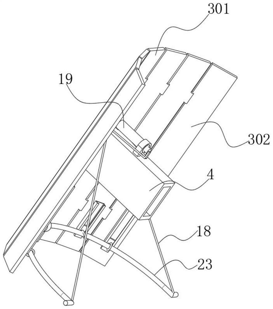
[0027] Refer Figure 1-4 A Wind solar lights, including a fixed bend at the top of lampposts rod 2, elbow and an end of the lever 2 away from the lamppost box 1 is fixed to the lower surface of the LED lamp box 12 is fixed to the top end of the fixed box there turn table 11, and the rotation table 11 rotatably connected to the top compression spring 10, a compression spring 10 is fixed to the top of the wind turbine, wind turbine comprises a wind power generator 7, the outer wall at the bottom end of the wind turbine 7 and the rotary table the upper surface 11 are fixed to a vertical metal rod 9, and one end of two metallic rod 9 are fixed to each other close to the nip contact 902 and a contact 901 hemisphere, engaging each other when the contacts 902 and a hemispherical when the normal contact 901 contacts the control circuit is closed, when the wind is too large, the compression spring 10 starts bending, at this time will intermeshing contact 902 and a contact 901 separate hemis...

Embodiment 2

[0035] Refer figure 1 and Figure 5 , A scenery complementary solar street lamp, this embodiment is compared to the first embodiment, and further includes a circumferential outer wall of the street lamp rod 1 to fix an insecticide box 17, and the outer wall of the deworming box 17 is close to the side of the street lamp rod 1. There is a rubber strip having an equal distance distribution in the inner side made of a spring steel material, so that it is possible to securely securely at any height of the streetlight rod 1 without using a helix when used.

[0036] Among them, the deworm box 17 is a rectangular structure of the inherent cavity, and the insecticulate box 17 is driven from the middle of the outer outer wall of the stream lever 1, and there are two mounting holes, and three mounting holes are sequentially fixed. 14 and grid 16, the insectoma 17 away from the inner wall of the grid 16 fixed to the traphic lamp plate 15, and the surface of the traphic lamp plate 15 sprinkles...


PUM


Abstract

The invention belongs to the technical field of street lamps, particularly relates to a wind-solar complementary solar street lamp. The invention aims to solve the problem that the stability of a street lamp is affected by an overlarge photovoltaic panel in the prior art. The wind-solar complementary solar street lamp comprises an elbow rod fixed to the top end of a street lamp pole; a lamp box is fixed to the end, away from the street lamp pole, of the elbow rod; an LED lamp is fixed to the lower surface of the lamp box; a rotating table is fixed to the top end of the lamp box; a compression spring is rotationally connected to the top end of the rotating table; and a wind generating set is fixed to the top end of the compression spring and comprises a wind driven generator. When the street lamp is used, an inclined photovoltaic panel can increase the overall wind resistance of the street lamp when wind power is too large, so that the stability of the street lamp is affected; and at the moment, a first contact and a hemispherical contact which are engaged with each other are driven to be separated, then a control circuit is disconnected, then a winding device obtains a signal, and the photovoltaic panel can be wound and surrounded on the elbow rod, so the overall wind resistance is reduced, and the solar street lamp is protected.

Description

Technical field [0001] The present invention relates to the field of lamp technology, and particularly to a solar wind and solar lights. Background technique [0002] Wind lights independent power supply system, which can effectively utilize the complementarity of wind and solar energy and time in common to the battery charging by both a respective generator. Voltage transmission line length of conventional lights, lights not only power, but also high power transmission lines. Conventional lights must Buried power cables, the power supply from the point at more than 3km roads they will build a supply line, if the illumination line extension, also need to set the boosting system, so most suburb road and highway away from the power points are not installation of street lights. [0003] The emergence of wind and solar lights to avoid the drawbacks of long-distance power street light, beautiful and unique wind and solar lights not only bring light to the city at night, and gave the c...

Claims


Application Information

Patent Timeline
Patent Type & Authority Applications(China)
IPC IPC(8): F21S9/02F21S9/03F21S9/04F21V23/00F21V33/00F21V15/00A01M1/04A01M1/22F21W131/103F21Y115/10
CPCF21S9/026F21S9/035F21S9/043F21V23/003F21V33/00F21V15/005A01M1/04A01M1/223F21W2131/103F21Y2115/10A01M2200/012Y02B20/72
Inventor 申旭
Owner 申旭
Learn More