
Reduced friction wind turbine apparatus and method

a wind turbine and friction reduction technology, applied in the direction of electric generator control, renewable energy generation, greenhouse gas reduction, etc., can solve the problems of inconsistency of wind and limited art, and achieve the effect of reducing drag and reducing wind resistan

Inactive Publication Date: 2007-06-26
NATURAL FORCES
View PDF18 Cites 33 Cited by
  • Summary
  • Abstract
  • Description
  • Claims
  • Application Information

AI Technical Summary

Benefits of technology

"The present invention is a wind-powered device that generates electricity using a floating mechanism and a flywheel to keep the generators spinning even when the wind speed is too low. The device also has a cowling to reduce drag and wind resistance, which increases the efficiency of the device. The technical effects of this invention are improved wind energy conversion and reduced drag and wind resistance, resulting in improved efficiency and power output."

Problems solved by technology

The art has been limited by at least two technical difficulties.
One is the inconsistency of the wind.
A corollary to this problem is overcoming the frictional resistance to supporting equipment that is large and massive enough to drive larger generating turbines.

Method used


Image

  • Reduced friction wind turbine apparatus and method
  • Reduced friction wind turbine apparatus and method
  • Reduced friction wind turbine apparatus and method

Examples


Embodiment Construction

[0017]The following description of the preferred embodiment(s) is merely exemplary in nature and is in no way intended to limit the invention, its application, or uses.

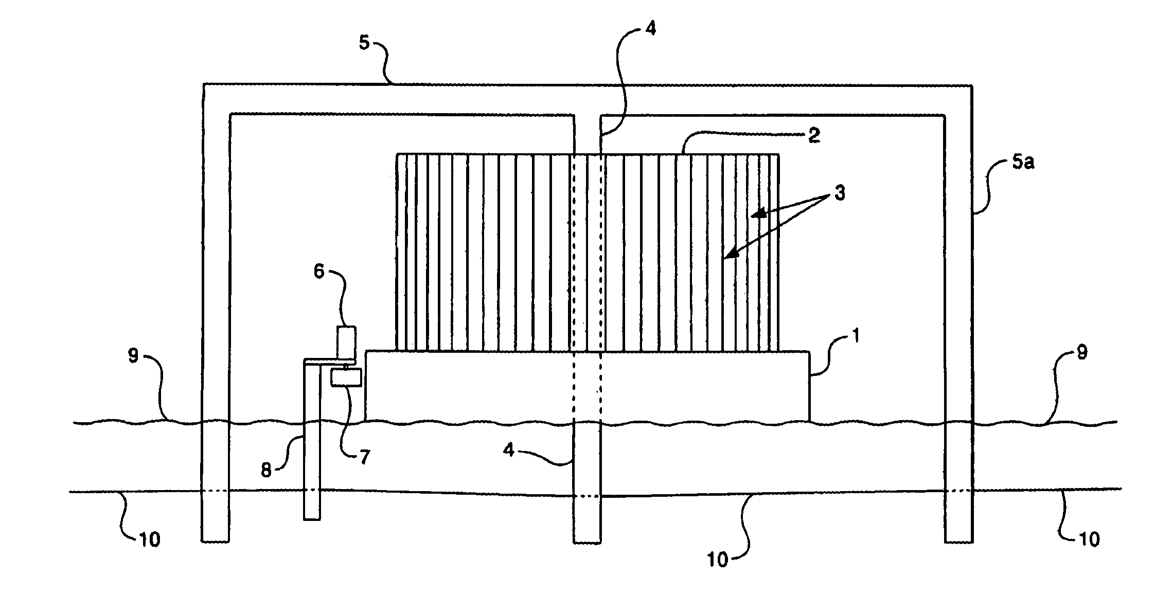
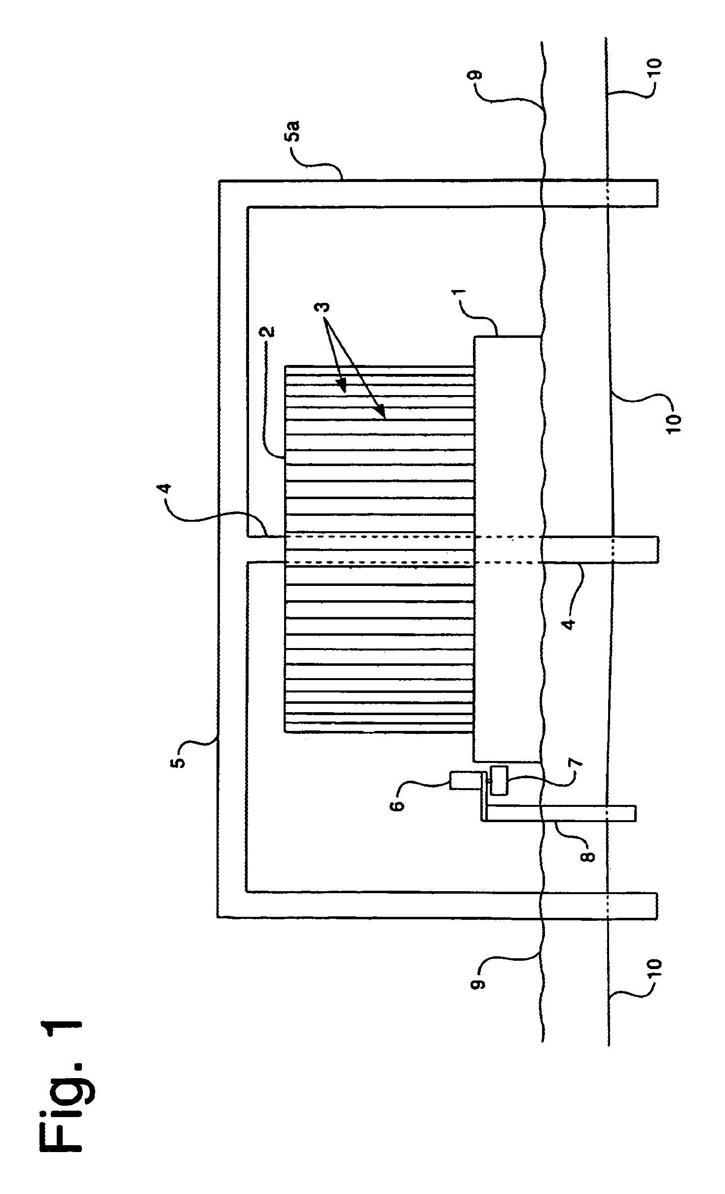
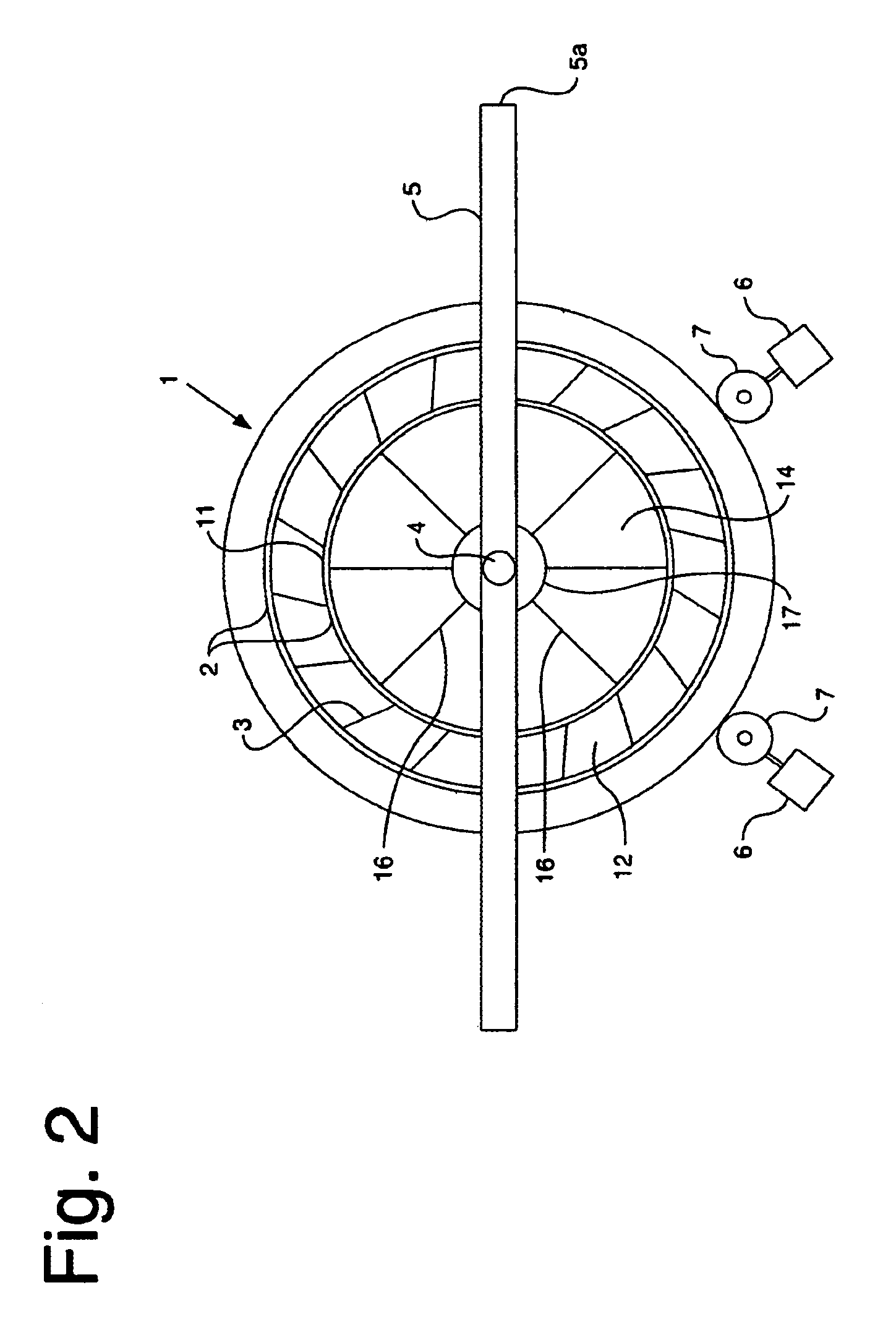
[0018]As illustrated in the drawings where like numerals represent like elements, FIGS. 1 and 2 depict the first embodiment of the present invention. A floating hull 1 is disposed to rest on a body of water 9. The body of water may be a preexisting naturally formed body water. Alternatively, the body of water 9 may be an artificially created pond, lagoon or the like disposed for support of the wind driven electricity generator.

[0019]Hull 1 has a positive displacement so that it floats on water. Hull 1 may be any size and weight, subject only to the limitation that it floats. Accordingly, hull 1 may be heavy and massive enough to serve as a flywheel. In the depicted embodiment, hull 1 is circular.

[0020]Hull 1 serves as a bottom mount for a plurality of vanes 3. The vanes are circularly arranged to form a fan. The type ...


PUM


Abstract

The present invention is a wind power apparatus for driving an electric generator. The wind power apparatus comprises a frame, a vertical axle mounted on the frame and a buoyant hull. The buoyant hull is rotational disposed on the axle. The buoyant hull has a curvilinear side surface. The wind power apparatus further comprises a fan. The fan is mounted on the buoyant hull such that wind rotating the fan rotates the buoyant hull. The wind power apparatus further has a drive wheel. The drive wheel is disposed in close cooperation with the curvilinear of the surface of the buoyant hull such that rotation of the buoyant hull rotates the drive wheel. The drive wheel is adapted to be in driving engagement with an electric generator such that rotation of the drive wheel turns the electric generator to generate electricity.

Description

CROSS-REFERENCE TO RELATED APPLICATIONS[0001]None.BACKGROUND OF THE INVENTION[0002]1. Field of the Invention[0003]The present invention is in the field of wind driven electricity generation.[0004]2. Related Art[0005]Wind as an alternate motive force for generating electricity has long provided an attractive alternative to conventional power generation techniques. The art has been limited by at least two technical difficulties. One is the inconsistency of the wind. Stated alternatively, there is a need in the art for extending the ability of wind driven electricity generation equipment to generate electricity beyond the time when the wind has dropped below velocities sufficient to turn generators. A corollary to this problem is overcoming the frictional resistance to supporting equipment that is large and massive enough to drive larger generating turbines.[0006]Both of the long standing needs have a common denominator; that is the increased friction resistance inherent in using large...

Claims


Application Information

Patent Timeline
Patent Type & Authority Patents(United States)
IPC IPC(8): F03D3/04
CPCF03D3/0472F05B2240/93Y02E10/74Y02E10/727F03D13/20F03D13/25F03D9/25
Inventor PLATT, MICHAEL D.
Owner NATURAL FORCES
Learn More