
Torsion spring and twisted rope winding drum assisting in winding up

A torsion spring and twisted rope technology, applied in the field of auxiliary hoisting devices, can solve problems such as inability to adjust, large torque, etc., and achieve the effect of compact structure, high torque, compact structure and stability

Pending Publication Date: 2021-12-17
WUHAN MARINE MACHINERY PLANT
View PDF9 Cites 0 Cited by
  • Summary
  • Abstract
  • Description
  • Claims
  • Application Information

AI Technical Summary

Problems solved by technology

[0004] The purpose of the present invention is to overcome that when the torsion spring existing in the prior art produces larger torsion force, its structure, size and weight are all relatively large and its torsion force cannot be adjusted; For the problem of installation matching, a twisted rope drum with torsion spring and auxiliary winding is provided

Method used


Image

  • Torsion spring and twisted rope winding drum assisting in winding up
  • Torsion spring and twisted rope winding drum assisting in winding up
  • Torsion spring and twisted rope winding drum assisting in winding up

Examples


Embodiment 1

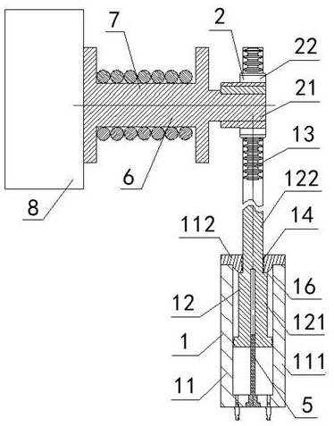
[0058] A torsion spring, the torsion spring includes an energy storage assembly 1 and a rotation assembly 2, the energy storage assembly 1 and the rotation assembly 2 are in transmission cooperation; the energy storage assembly 1 includes a closed cylinder 11 and a piston rod 12, the The inside of the cylinder 11 is provided with a piston 15, the piston 15 is in sealing fit with the inner wall of the cylinder 11, the piston 15 is fixedly connected with one end of the piston rod 12, and the other end of the piston rod 12 passes through the cylinder 11 and connects with the cylinder 11. The rack 13 is fixedly connected; the rotating assembly 2 includes a rotating shaft 21 and a cylindrical gear 22, the cylindrical gear 22 is fixedly arranged on the rotating shaft 21, and the cylindrical gear 22 meshes with the rack 13; the cylinder 11 includes a cylinder seal cover 112 and a cylinder 111 with an opening at one end, the cylinder sealing cover 112 is in sealing fit with the opening...

Embodiment 2

[0060] Embodiment 2 is basically the same as Embodiment 1, and its difference is:

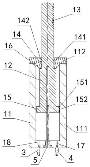
[0061] One end of the cylinder body 111 far away from the cylinder sealing cover 112 is provided with an inflation port 17 and a detection port 18, the inflation port 17 is provided with an inflation valve 4, and the detection port 18 is provided with a pressure sensor 3; A piston displacement sensor 5 is arranged between the charging port 17 and the detection port 18 .

Embodiment 3

[0063] Embodiment 3 is basically the same as Embodiment 2, and its difference is:

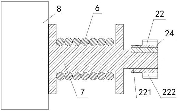
[0064]The rotating cylinder 7 is also provided with a reduction mechanism 23, and the rotating shaft of the rotating cylinder 7 is connected with the rotating shaft 21 and the cylindrical gear 22 through the reducing mechanism 23; the cylindrical gear 22 includes a gear inner ring 221 and a gear outer ring 222. The outer gear ring 222 is fixedly disposed outside the inner gear ring 221 , and the inner gear ring 221 is fixedly connected to the rotating shaft 21 through the connecting key 24 .


PUM


Abstract

The invention discloses a torsion spring. The torsion spring comprises an energy storage assembly and a rotating assembly, wherein the energy storage assembly is in transmission fit with the rotating assembly, the energy storage assembly comprises a closed cylinder barrel and a piston rod, a piston is arranged in the cylinder barrel, the piston is in sealing fit with the inner wall of the cylinder barrel, the piston is fixedly connected with one end of the piston rod, and the other end of the piston rod penetrates through the cylinder barrel and then is fixedly connected with a rack; and the rotating assembly comprises a rotating shaft and a cylindrical gear, the cylindrical gear is fixedly arranged on the rotating shaft, and the cylindrical gear is meshed with the rack. The twisted rope winding drum assisting in winding up comprises the torsion spring, a rotating drum and a twisted rope wound on the rotating drum, wherein one end of a rotating shaft of the rotating drum is in transmission fit with a main power output device, and the other end of the rotating shaft of the rotating drum is in transmission fit with the cylindrical gear. The torsion of the torsion spring in the design is adjustable; installing and debugging are easy; and the torsion spring provides a winding-up assisting function for the twisted rope winding drum, so that the power requirement for a motor can be reduced.

Description

technical field [0001] The invention relates to an auxiliary hoisting device, in particular to a torsion spring and a twisted rope reel for auxiliary hoisting, which is particularly suitable for reducing the power demand of a marine twisted rope reel for a motor. Background technique [0002] Torsion springs can store and release rotational energy. When components rotate around the center, torsion springs can generate torque, prompting components to generate corresponding rotational torque, and are widely used in the field of mechanical engineering. [0003] This design is aimed at a special marine twisted rope reel, and it is expected that the torsion spring can play a certain role in auxiliary winding during the rope twisting process, so as to reduce the power demand for the motor. However, the conventional torsion spring needs to generate a large torsion force in the process of assisting the winding up. If the traditional torsion spring is used, the structure, size and we...

Claims


Application Information

Patent Timeline
Patent Type & Authority Applications(China)
IPC IPC(8): B66D1/28B66D1/30B66D1/54B66D1/14F15B15/28
CPCB66D1/28B66D1/30B66D1/54B66D1/14F15B15/2838
Inventor 刘帅孟华曾文则许东周虎罗杰
Owner WUHAN MARINE MACHINERY PLANT
Learn More