Metal plate cutting device
A technology for cutting devices and metal sheets, applied in the direction of shearing devices, shearing machine accessories, feeding devices, etc., can solve the problems of inconvenient use, low processing efficiency, time-consuming and labor-intensive metal sheets, etc., to avoid uneven force , High processing efficiency, easy reset effect
- Summary
- Abstract
- Description
- Claims
- Application Information
AI Technical Summary
Problems solved by technology
Method used
Image


Examples
Embodiment 1
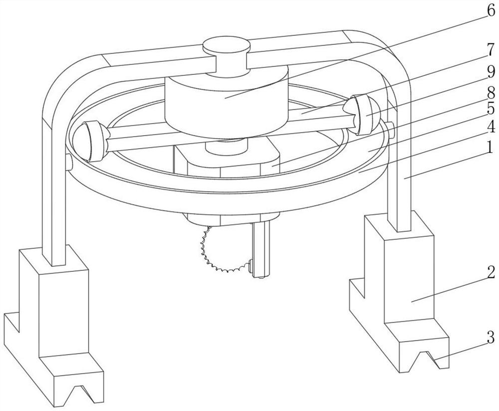
[0039] see Figure 1-3 , the present invention provides a technical solution: a sheet metal cutting device, specifically comprising:
[0040] A bracket 1, the bottom of both ends of the bracket 1 is provided with a lifting platform 2, and the bottom of the lifting platform 2 is provided with a fixing groove 3;
[0041] A support ring 4, the top of the support ring 4 is provided with a chute 5, and the two ends of the support ring 4 are fixed on the bracket 1 through a fixing rod;
[0042] Rotating device 6, the top of the rotating device 6 is fixedly connected to the center position of the top of the bracket 1, the bottom of the rotating device 6 is provided with a horizontal slideway 7, and the bottom of the horizontal slideway 7 is slidingly connected with a cutting device 8;
[0043] Sliding support device 9, the sliding support device 9 is arranged at both ends of the horizontal slideway 7, the bottom of the sliding support device 9 extends to the inside of the chute 5 an...
Embodiment 2
[0051] see Figure 1-4 On the basis of Embodiment 1, the present invention provides a technical solution: the sliding support device 9 includes a connecting rod 91, one end of the connecting rod 91 is provided with a first stopper 92 and a second stopper 93, and the connecting rod 91 is located at the first The part between the first stopper 92 and the second stopper 93 is connected with a rotating ring 94 through ball rotation, and the outer side of the rotating ring 94 is provided with a protective pad 95, and the end of the connecting rod 91 away from the first stopper 92 is fixed to the horizontal slideway 7 Connection, the connecting rod 91 is threadedly connected with the second block 93, and a sliding support device 9 is provided. When the cutting device 8 rotates, the cross slide 7 needs to rotate together with the cutting device 8. When the cross slide 7 rotates, it can pass through the slide support device. 9 and the support ring 4 support the two ends of the slidewa...
Embodiment 3
[0053] see Figure 1-5 On the basis of Embodiment 1 and Embodiment 2, the present invention provides a technical solution: the bottom of the cutting device 8 is slidingly connected with a telescopic baffle 81, and the top of the telescopic baffle 81 extends to the inside of the cutting device 8 and is slidably connected with the cutting device 8 One side of the telescopic baffle 81 is provided with a retaining groove 82, the inner wall of the retaining groove 82 is provided with a buffer pad 83, the bottom of the telescopic baffle 81 is provided with a roller 84, and one side of the cutting knife of the cutting device 8 extends to the inside of the retaining groove 82, and the cutting device The rotation direction of the cutting knife on the 8 is towards the telescopic baffle 81. When the cutting knife on the cutting device 8 is cutting the plate, the sparks generated can be blocked by the telescopic baffle 81 to avoid splashing of sparks, which is safe to use, and the inside o...
PUM
 Abstract
Description
Claims
Application Information
 - R&D
- Intellectual Property
- Life Sciences
- Materials
- Tech Scout
- Unparalleled Data Quality
- Higher Quality Content
- 60% Fewer Hallucinations
Browse by: Latest US Patents, China's latest patents, Technical Efficacy Thesaurus, Application Domain, Technology Topic, Popular Technical Reports.
© 2025 PatSnap. All rights reserved.Legal|Privacy policy|Modern Slavery Act Transparency Statement|Sitemap|About US| Contact US: help@patsnap.com