
Follow-up permanent magnetic field arc extinguishing mechanism in double-breakpoint direct-acting contactor

A permanent magnetic field, direct-acting technology, applied in the direction of relays, electromagnetic relays, detailed information of electromagnetic relays, etc., can solve the problems of reduced voltage withstand insulation performance of devices, lack of arc extinguishing magnetic field, variable size, and fast diffusion of charged particles. , to achieve the effect of fast extinguishing speed, avoiding too slow arcing speed, and high withstand voltage insulation performance

Active Publication Date: 2021-12-10
HARBIN INST OF TECH
View PDF3 Cites 0 Cited by
  • Summary
  • Abstract
  • Description
  • Claims
  • Application Information

AI Technical Summary

Problems solved by technology

If the magnetic induction intensity B of the arc extinguishing magnetic field is too small, the arcing speed will be slow, and if the magnetic induction intensity B of the arc extinguishing magnetic field is too large, the charged particles will diffuse too fast. The drop is too fast; therefore, during the breaking process, the magnitude of the arc extinguishing magnetic field should be variable
At present, there is a lack of methods to make the magnitude of the arc extinguishing magnetic field variable in the structure of the arc extinguishing device

Method used

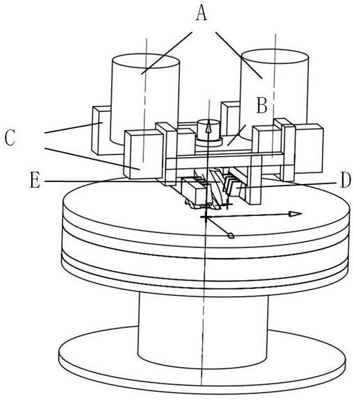

Image

  • Follow-up permanent magnetic field arc extinguishing mechanism in double-breakpoint direct-acting contactor
  • Follow-up permanent magnetic field arc extinguishing mechanism in double-breakpoint direct-acting contactor
  • Follow-up permanent magnetic field arc extinguishing mechanism in double-breakpoint direct-acting contactor

Examples


Embodiment Construction

[0016] The technical solution of the present invention will be further described below in conjunction with the accompanying drawings, but it is not limited thereto. Any modification or equivalent replacement of the technical solution of the present invention without departing from the spirit and scope of the technical solution of the present invention should be covered by the present invention. within the scope of protection.

[0017] The present invention provides a design method of a servo permanent magnet magnetic field arc extinguishing mechanism applied in a double breakpoint direct-acting contactor arc extinguishing system. The design idea includes the following points:

[0018] 1. Using the typical magnetic blowout method, the permanent magnets are respectively placed on both sides of the gap between the moving and static contacts. The magnetic field generated by them will cause the arc to be driven by electromotive force, thus elongating to both sides, and the arc will ...


PUM


Abstract

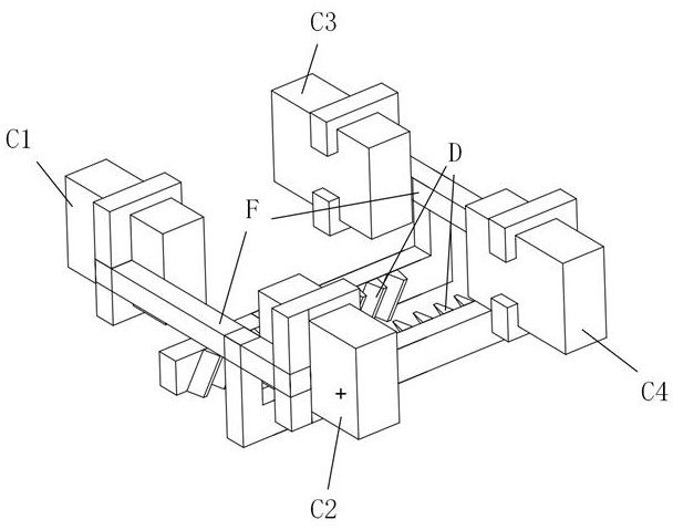
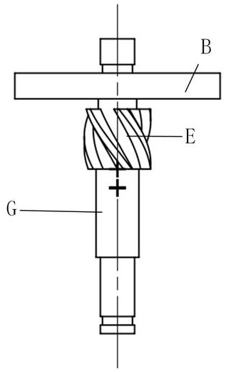
The invention discloses a follow-up permanent magnetic field arc extinguishing mechanism in a double-breakpoint direct-acting contactor. The arc extinguishing mechanism comprises a moving contact, a static contact, permanent magnets, a rack, a gear, a support and a connecting rod, wherein the moving contact and the gear are fixed at the upper part of the connecting rod, and the permanent magnets comprise a first permanent magnet, a second permanent magnet, a third permanent magnet and a fourth permanent magnet. The first permanent magnet and the second permanent magnet are fixed on the first support; the third permanent magnet and the fourth permanent magnet are fixed on the second support; the first support and the second support are respectively connected with two connecting rods with racks, front-back movement of the permanent magnets is associated with up-down movement of the moving contact through gear and rack transmission, the distance between the permanent magnets on the two sides is changed along with movement of the moving contact, and therefore the size of an arc extinguishing magnetic field is changed. The problems that the arcing speed is too low in the arcing stage and the insulation and voltage resistance of the device is reduced too fast in the arcing stage are avoided, so that the arc extinguishing speed between the contacts of the contactor is higher, and the higher voltage resistance and insulation performance is kept.

Description

technical field [0001] The invention belongs to the technical field of contactors, and relates to a device for extinguishing arcs by using a permanent magnetic field that can move with the movement of an armature. Background technique [0002] When the circuit is broken in the atmosphere, if the breaking current and the voltage between the contacts after breaking are greater than the arcing current and arcing voltage, an arc will be generated between the contacts. For switching appliances, the existence of arcs will delay circuit breaking, burn contacts, and in severe cases may cause fire and explosion of switching appliances. Therefore, how to extinguish the arc as soon as possible is a key point for researchers. Magnetic blowout arc extinguishing is a typical arc extinguishing device, which uses electromotive force to drive the arc to elongate horizontally, so that the arc voltage increases, the volt-ampere characteristics of the arc leave the stable combustion point, and...

Claims


Application Information

Patent Timeline
Patent Type & Authority Applications(China)
IPC IPC(8): H01H50/54H01H50/64
CPCH01H50/54H01H50/64
Inventor 乔瑜菲由佳欣周成龙张永健蒲永亮朱月霖
Owner HARBIN INST OF TECH
Learn More