Concrete slump detection device
A detection device and slump technology, which are applied in the field of concrete slump detection devices, can solve the problems of difficult control, easy to touch concrete, time-consuming and laborious concrete compaction degree, etc., and achieve high verticality, ensure accuracy, and move smooth effect
- Summary
- Abstract
- Description
- Claims
- Application Information
AI Technical Summary
Problems solved by technology
Method used
Image
Examples
Embodiment 1
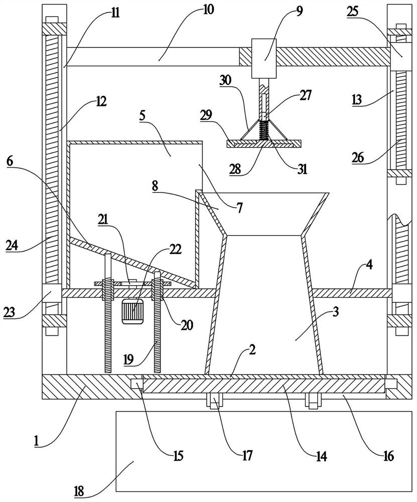
[0023] Such as figure 1 Shown, a kind of concrete slump detection device, it comprises support base 1, and the upper surface of described support base 1 is provided with support base plate 2, and the upper surface of described support base plate 2 is provided with detection cylinder 3, and described detection cylinder The outer surface of 3 is connected with a support beam A4, the outer end of the support beam A4 is connected with the lifting mechanism A, and the two ends of the support beam A4 are respectively connected to the guide groove A12 on the inner surface of the support column 11 by sliding up and down. , the support column 11 is fixedly connected to the upper surface of the support base 1, and the lifting mechanism A can drive the support beam A4 and the detection cylinder 3 to move vertically along the guide groove A12, preventing the manual lifting of the detection cylinder 3 due to the detection cylinder 3 bumps into concrete, thereby affecting the accuracy of th...
Embodiment 2
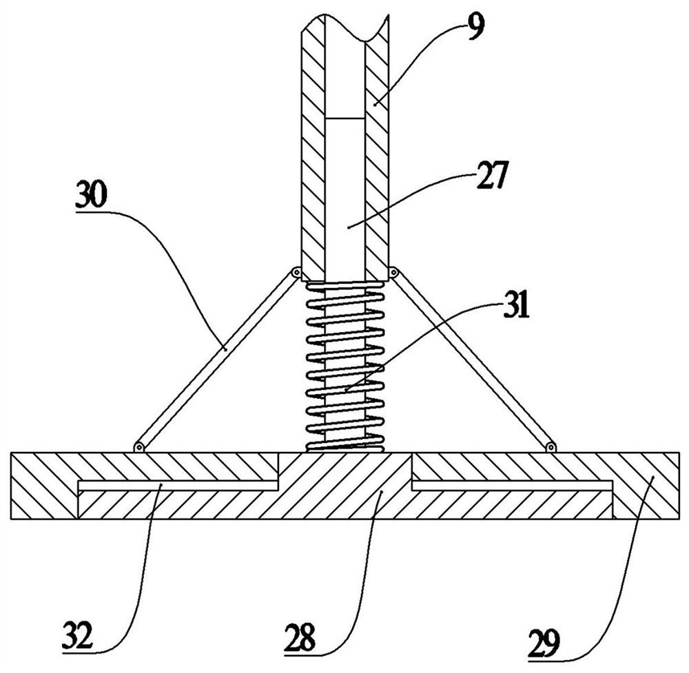
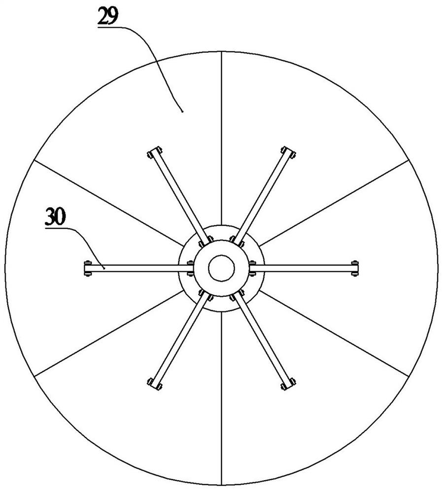
[0025] Such as Figure 1-3Shown, a kind of concrete slump detection device, it comprises support base 1, and the upper surface of described support base 1 is provided with support base plate 2, and the upper surface of described support base plate 2 is provided with detection cylinder 3, and described detection cylinder The outer surface of 3 is connected with support beam A4, and the outer end of described support beam A4 links to each other with elevating mechanism A, and described elevating mechanism A comprises the slider A23 that is fixed on the outer end of support beam A4 and slides A23 through screw thread. The threaded rod B24 for connection, the threaded rod B24 is connected in rotation with the support column 11, and the slider A23 is slidingly connected with the guide groove A12 up and down. By driving the threaded rod B24 to rotate, the slider A23 can drive the detection cylinder 3 Move vertically along the axial direction of the threaded rod B24 to achieve a smoo...
PUM
 Abstract
Description
Claims
Application Information
 - R&D
- Intellectual Property
- Life Sciences
- Materials
- Tech Scout
- Unparalleled Data Quality
- Higher Quality Content
- 60% Fewer Hallucinations
Browse by: Latest US Patents, China's latest patents, Technical Efficacy Thesaurus, Application Domain, Technology Topic, Popular Technical Reports.
© 2025 PatSnap. All rights reserved.Legal|Privacy policy|Modern Slavery Act Transparency Statement|Sitemap|About US| Contact US: help@patsnap.com


