Water taking device suitable for different depths

A water dispenser and depth technology, applied in instruments, sampling, sampling devices, etc., can solve the problems of time-consuming and labor-intensive, inaccurate sampling, and large deviation from the sampling position, saving time, avoiding leakage, and ensuring sampling. Effect

Pending Publication Date: 2021-12-07
姚军
View PDF0 Cites 2 Cited by
  • Summary
  • Abstract
  • Description
  • Claims
  • Application Information

AI Technical Summary

Problems solved by technology

[0003] However, the existing underwater sampling device still has the following deficiencies in the actual use process: when the traditional water fetcher is in use, the water fetcher is fixed by a rope and slowly put into the water body, and it sinks by its own weight until the water fetcher reaches the water body. Open the sampler for sampling at a predetermined depth, but this method is only suitable for still water bodies with gentle water flow. Once the water flow in the water body is too large, the water collector will move laterally under the impact of the water flow, so that the traction rope will tilt with the water collector , leading to the water fetcher not only difficult to reach the predetermined depth, but also a large deviation from the sampling position, resulting in inaccurate sampling and affecting the detection effect; It is time-consuming and labor-intensive, especially in waters with large water impacts. Not only is it more time-consuming and labor-intensive, it seriously affects the water intake efficiency, and the water dispenser is prone to shaking and vibration when it is impacted by the water flow. It is difficult to ensure the integrity of the water dispenser after sampling. Sealing, the samples inside the water storage chamber inside the upper shell are extremely vulnerable to external pollution

Method used


Image

  • Water taking device suitable for different depths
  • Water taking device suitable for different depths
  • Water taking device suitable for different depths

Examples


Embodiment Construction

[0019] The following will clearly and completely describe the technical solutions in the embodiments of the present invention with reference to the accompanying drawings in the embodiments of the present invention. Obviously, the described embodiments are only some, not all, embodiments of the present invention. Based on the embodiments of the present invention, all other embodiments obtained by persons of ordinary skill in the art without making creative efforts belong to the protection scope of the present invention.

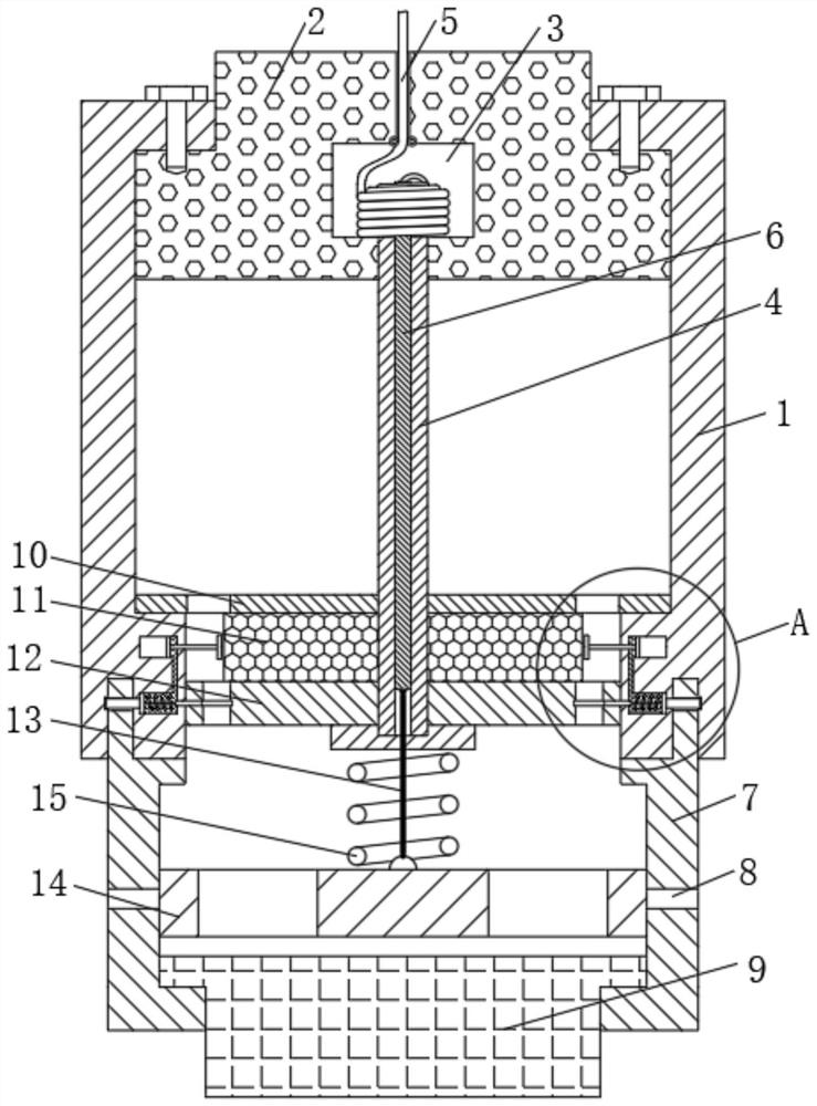
[0020] see Figure 1-2 , a water dispenser suitable for different depths, comprising an upper casing 1, the upper end of the upper casing 1 is fixedly connected with a floating block 2, the inside of the floating block 2 is provided with a cavity 3, and the middle part of the cavity 3 is fixedly connected with a middle Empty pipe 4, the middle part of the hollow pipe 4 is movably connected with a straight rod 6, the upper end of the straight rod 6 is fixedly c...


PUM


Abstract

The invention relates to the technical field of water quality detection, and discloses a water taking device suitable for different depths. The water taking device comprises an upper shell, the upper end of the upper shell is fixedly connected with a floating block, the floating block is internally provided with a cavity, the middle part of the cavity is fixedly connected with a hollow pipe, and the middle part of the hollow pipe is movably sleeved with a straight rod. Through the arrangement of the floating block, a balancing weight, a pull rope and a clamping block, the water taking device can automatically and vertically sink to the preset depth by means of the gravity of the water taking device, the sampling accuracy can be ensured, sampling is automatically started after the preset depth is reached, the water taking device can be separated from a lower shell after sampling is completed, and the upper shell can automatically float upwards along the pull rope under the action of the floating block to complete sampling, so that a worker only needs to fix the upper end of the pull rope and put down the water taking device in the whole water taking process of the water taking device, the water taking process can be completed by means of the water taking device, the time of the worker is saved, the worker does not need to pull the water taking device up by himself / herself, and the device is more efficient and convenient.

Description

technical field [0001] The invention relates to the technical field of water quality detection, in particular to a water fetcher suitable for different depths. Background technique [0002] Water quality sampling is mainly to collect water samples in water bodies. When testing the water quality of rivers, lakes and other water bodies in water level survey work, it is required to sample and analyze water bodies at different locations and at different depths. [0003] However, the existing underwater sampling device still has the following deficiencies in the actual use process: when the traditional water fetcher is in use, the water fetcher is fixed by a rope and slowly put into the water body, and it sinks by its own weight until the water fetcher reaches the water body. Open the sampler to take samples at a predetermined depth, but this method is only suitable for still water bodies with gentle water flow. Once the water flow in the water body is too large, the water colle...

Claims


Application Information

Patent Timeline
IPC IPC(8): G01N1/10B63B35/00
CPCG01N1/10B63B35/00G01N2001/1031
Inventor 姚军
Owner 姚军
Why Eureka
Try Eureka