Light source detection device

A technology for testing equipment and light sources, applied in photometry, optical instrument testing, optical radiation measurement, etc., can solve problems affecting heating efficiency, light source attenuation, etc., and achieve the effect of improving overexposure and shading effect

Pending Publication Date: 2021-12-07
ADVANCED ION BEAM TECHNOLOGY INC
View PDF0 Cites 0 Cited by
  • Summary
  • Abstract
  • Description
  • Claims
  • Application Information

AI Technical Summary

Problems solved by technology

Usually under long-term use, the light source may attenuate and affect the heating performance, so regular inspection is required

Method used


Image

  • Light source detection device
  • Light source detection device
  • Light source detection device

Examples


Embodiment Construction

[0035] Various embodiments of the present invention will be described in detail below, and illustrated with illustrations. In the description of the specification, many specific details are provided in order to enable readers to have a more complete understanding of the present invention; however, the present invention may still be practiced under the premise of omitting some or all of the specific details. The same or similar elements will be denoted by the same or similar symbols in the drawings. It should be noted that the illustrations are for illustrative purposes only, and do not represent the actual size or quantity of components, and some details may not be fully drawn for simplicity of the illustrations.

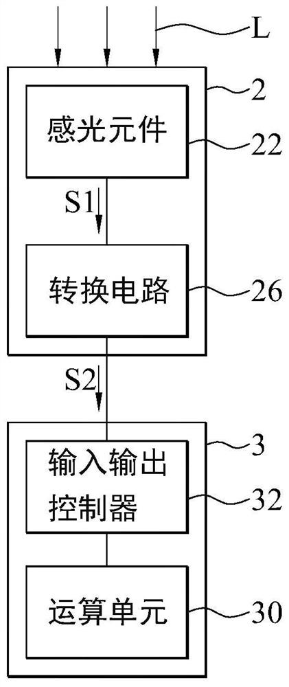
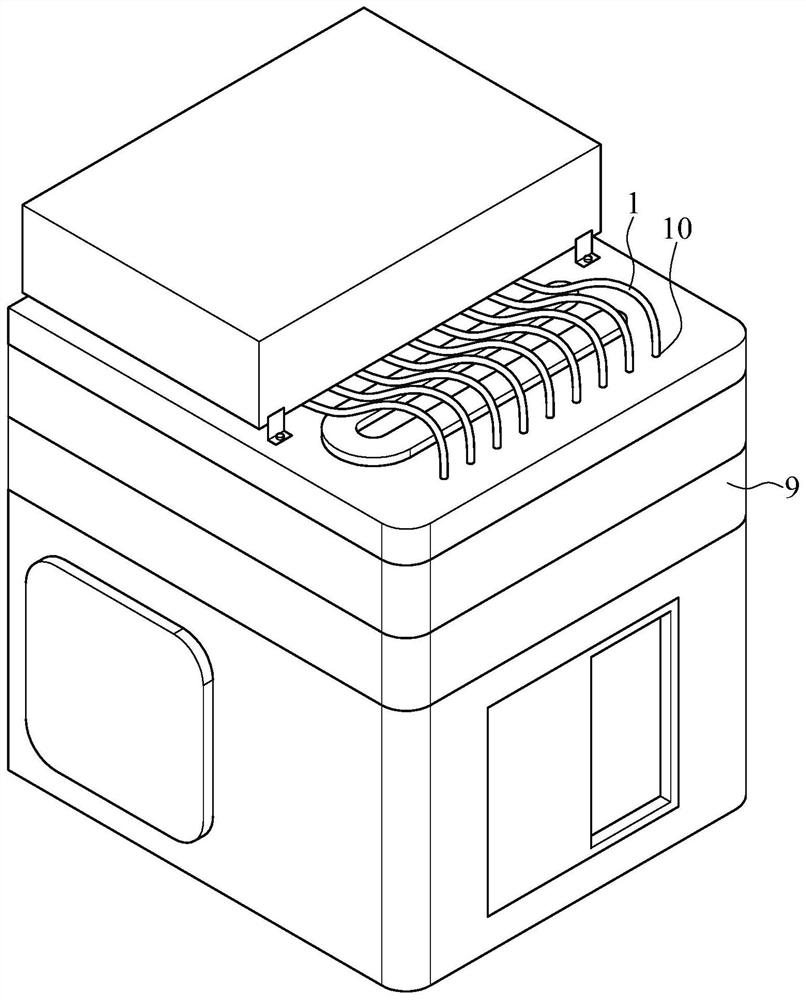
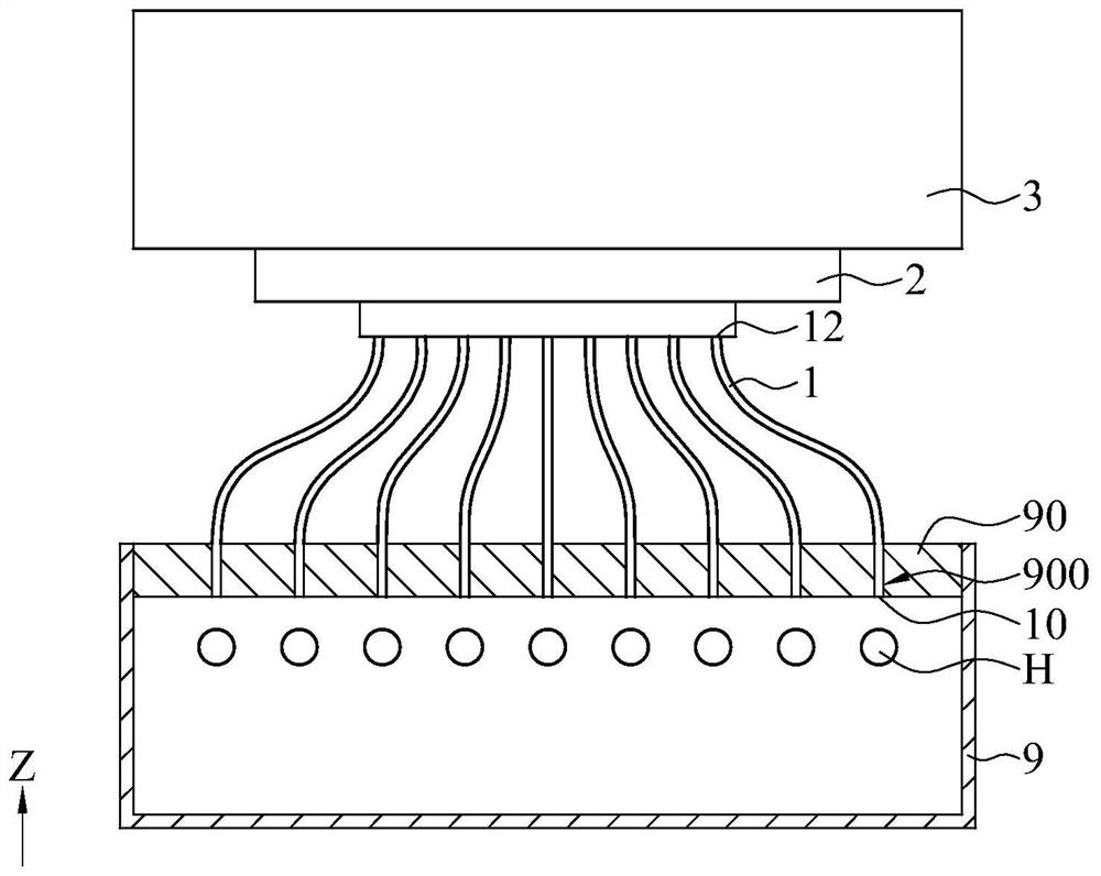
[0036] figure 1 It is a functional block diagram of a light source detection device according to some embodiments of the present invention. figure 2 It is a three-dimensional schematic diagram of a light source detection device according to some embodiments of th...


PUM


Abstract

A light source detection device comprises a plurality of optical fibers, a light sensing module and a processing module. Each optical fiber receives light from each light source through the light input end and outputs the light to the light output end. The photosensitive module comprises a circuit board, a plurality of photosensitive elements, a light blocking structure and a conversion circuit. Each photosensitive element receives light from each light output end and generates a corresponding light signal. The light blocking structure is located around the plurality of photosensitive elements and is connected to the light output end of each optical fiber. The conversion circuit receives the optical signal and generates a corresponding electrical signal. The processing module compares the electric signal with a preset value and calculates a light intensity change value corresponding to each light source.

Description

technical field [0001] The invention relates to a light source detection device, in particular to a light source detection device suitable for real-time monitoring of a light source in a cavity. Background technique [0002] In some semiconductor processes, the wafer or workpiece (workpiece) can go through a preheating step to a specific working condition before implementing the ion implantation process, and can also go through a heating step to return to normal temperature after completing the low temperature process. Generally speaking, in the above-mentioned heating method, the temperature of the light source inside the cavity can reach more than 1,000 degrees Celsius after being turned on, and then radiate heat toward the element to realize the heating mechanism, that is, drive the light source in the cavity as a heat source to provide heat energy To change the temperature in the cavity to meet the temperature conditions required by a specific process. Usually, under lo...

Claims


Application Information

Patent Timeline
IPC IPC(8): G01M11/02G01J1/42G01J1/04
CPCG01M11/02G01M11/0207G01J1/4257G01J1/0425
Inventor 陈建利胡瑞沧冯建大
Owner ADVANCED ION BEAM TECHNOLOGY INC
Why Eureka
Try Eureka