
Simple buffer tank and application thereof

A buffer tank and simple technology, applied in the field of buffer tanks, can solve the problems of increased pipeline pressure, human injury, improper operation, etc., to achieve the effect of strengthening the buffer effect, changing the buffer time, and ensuring cleanliness

Pending Publication Date: 2021-12-07
CHINA NAT CHEM ENG THIRD CONSTR
View PDF11 Cites 1 Cited by
  • Summary
  • Abstract
  • Description
  • Claims
  • Application Information

AI Technical Summary

Problems solved by technology

[0002] In chemical, petrochemical and other installation projects, there is a procedure to test the welding quality of the pipeline and the installation quality of the pipeline during the pipeline construction process. This procedure is the pressure test. The pipeline pressure test is a construction activity with a high risk factor. Improper operation can easily cause security incident
[0003] In general, the pipeline should be divided into pressure test packages according to the pressure level. The pressure test package involves multiple pipelines. Using a pressure test pump to directly connect with the pressure test package for pressure testing may cause the pipeline pressure to rise rapidly and the pressure gauge is easily damaged. An accident in the pipeline pressure test system caused harm to the human body

Method used


Image

  • Simple buffer tank and application thereof
  • Simple buffer tank and application thereof
  • Simple buffer tank and application thereof

Examples


Embodiment 1

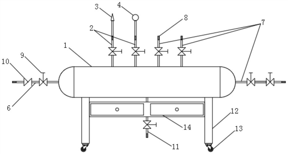
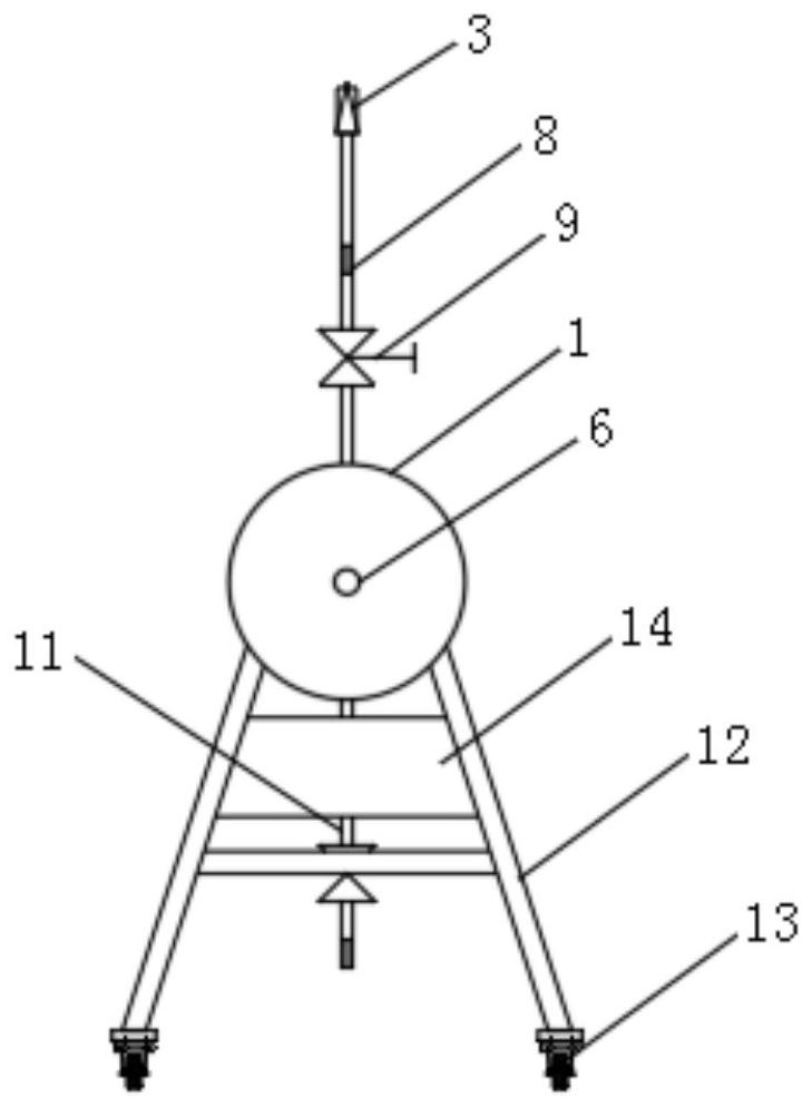
[0028] Such as Figure 1-3 As shown, a simple buffer tank includes a tank body 1, a safety valve 3 connected to the tank body 1 through a branch pipe 2, a pressure gauge 4, and a tank cavity volume adjustment assembly 5 installed in the tank body 1; The tank body 1 includes a tube body and a cap, and the caps are welded to both ends of the tube body to form a capsule-shaped tank body 1; one of the tube caps is connected to the inlet tube 6, and the other tube cap is connected to the tube 6. And the pipe body is respectively connected with one and several outlet pipes 7, the bottom of the pipe body is connected with the sewage pipe 11, and one end of the inlet pipe 6, the outlet pipe 7, the branch pipe 2, and the sewage pipe 11 is provided with a short pipe 8 connected with a wire, The branch pipe 2 is connected to the safety valve 3 and the pressure gauge 4 through a short wire connection pipe 8 at one end, and a stop valve is arranged on the branch pipe 2, the inlet pipe 6, t...


PUM


Abstract

The invention relates to a simple buffer tank which comprises a tank body, a safety valve connected with the tank body through a branch pipe, a pressure gauge and a tank cavity volume adjusting assembly installed in the tank body. The tank cavity volume adjusting assembly comprises an air inlet pipe, an air bag fixed in the middle of an inner cavity of the tank body and communicated with the air inlet pipe and an inflation and deflation mechanism connected with the air inlet pipe, and the air bag is enlarged / shrunk in the tank body under the inflation / deflation work of the inflation and deflation mechanism so as to adjust the volume of the tank body. The buffer tank is applied to a pipeline pressure testing system, an inlet pipe is connected with a pressure testing pump, and an outlet pipe is connected with a pressure testing bag. The buffer tank with the safety valve is connected between the pressure testing pump and the pressure testing bag, the pressure testing mode that the pressure testing pump and the pressure testing bag are directly connected is broken, the pipeline pressure testing system with the buffer tank can guarantee normal pressure in the system, accidental injury caused by damage of a pressure gauge is avoided, the volume of the tank body is changed through inflation and deflation of the air bag, buffering time can be changed, and the buffer tank is suitable for pipeline pressure testing with different requirements.

Description

technical field [0001] The invention belongs to the technical field of buffer tanks, and in particular relates to a simple buffer tank and its application. Background technique [0002] In chemical, petrochemical and other installation projects, there is a procedure to test the welding quality of the pipeline and the installation quality of the pipeline during the pipeline construction process. This procedure is the pressure test. The pipeline pressure test is a construction activity with a high risk factor. Improper operation can easily cause security incident. [0003] In general, the pipeline should be divided into pressure test packages according to the pressure level. The pressure test package involves multiple pipelines. Using a pressure test pump to directly connect with the pressure test package for pressure testing may cause the pipeline pressure to rise rapidly and the pressure gauge is easily damaged. An accident occurred in the pipeline pressure test system, cau...

Claims


Application Information

Patent Timeline
IPC IPC(8): F17D5/08F16L55/027B08B9/087
CPCF17D5/08F16L55/027B08B9/087Y02A20/00
Inventor 李臣涛
Owner CHINA NAT CHEM ENG THIRD CONSTR
Learn More