
Road bridge joint cutting device

A bridge-use and seam-cutting technology, which is applied in the field of road machinery, can solve problems such as inconvenient adjustment, cutting deviation, and space occupation, and achieve the effects of convenient centralized control, improved cutting efficiency, and extended service life

Pending Publication Date: 2021-12-07
谢伟光
View PDF5 Cites 0 Cited by
  • Summary
  • Abstract
  • Description
  • Claims
  • Application Information

AI Technical Summary

Problems solved by technology

[0004] The purpose of the present invention is to provide a cutting device for road bridges in order to solve the problems of (deviation in cutting, space occupation, inconvenient adjustment)

Method used


Image

  • Road bridge joint cutting device
  • Road bridge joint cutting device
  • Road bridge joint cutting device

Examples


Embodiment Construction

[0028] In order to make the object, technical solution and advantages of the present invention clearer, the present invention will be further described in detail below in conjunction with the accompanying drawings and embodiments. It should be understood that the specific embodiments described here are only used to explain the present invention, not to limit the present invention.

[0029] In the description of the present invention, it should be noted that the terms "center", "upper", "lower", "left", "right", "vertical", "horizontal", "inner", "outer" etc. The indicated orientation or positional relationship is based on the orientation or positional relationship shown in the drawings, and is only for the convenience of describing the present invention and simplifying the description, rather than indicating or implying that the referred device or element must have a specific orientation, or in a specific orientation. construction and operation, and therefore cannot be constru...


PUM


Abstract

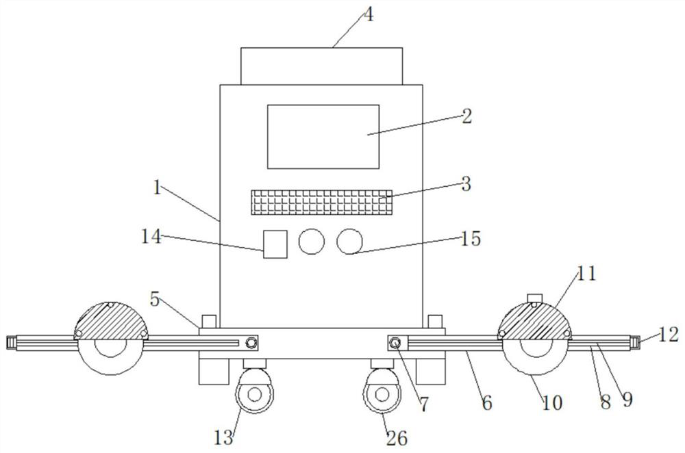
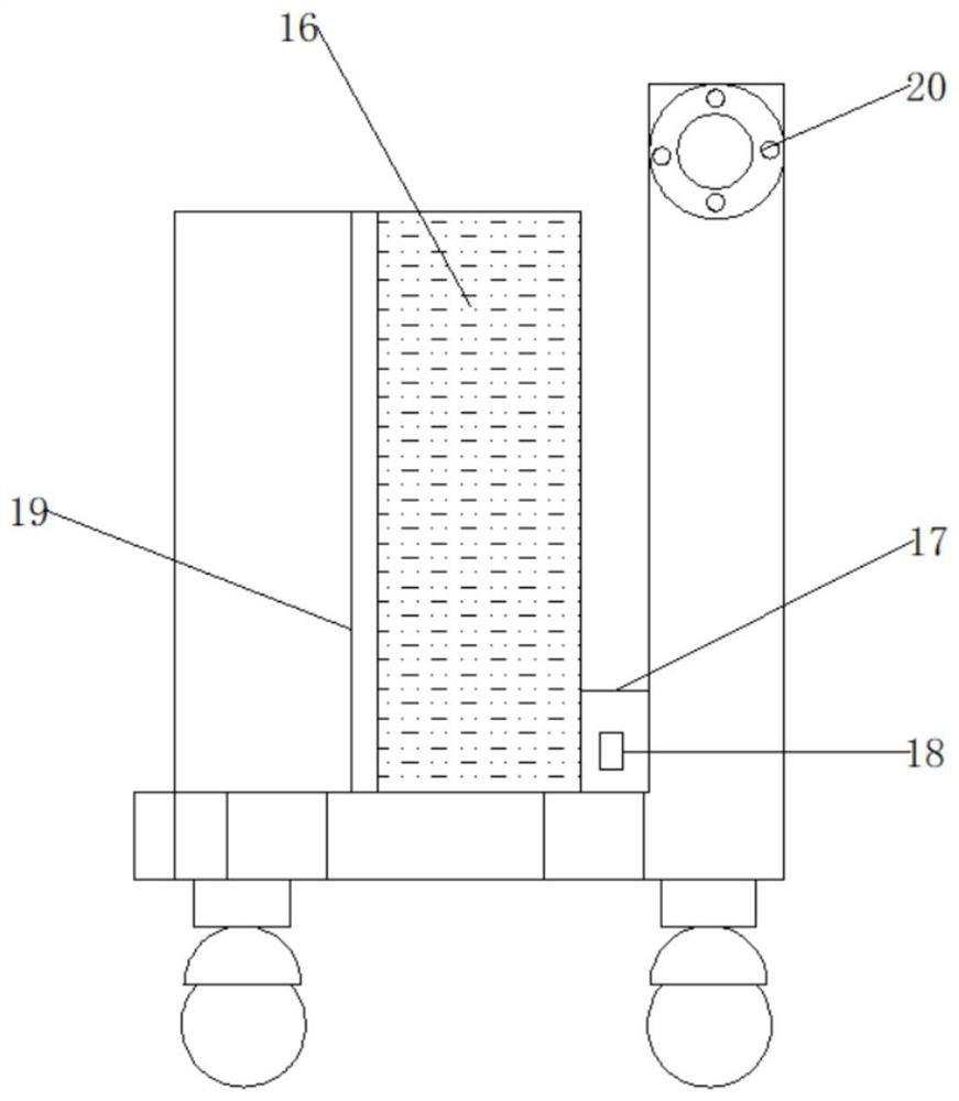
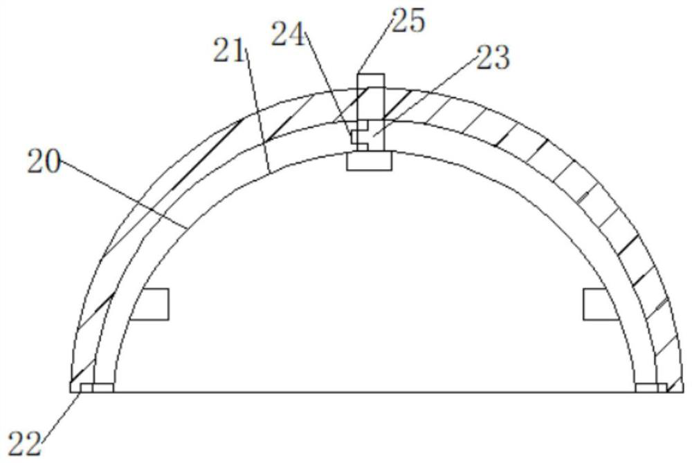
The invention discloses a road bridge joint cutting device. The road bridge joint cutting device comprises a control body, a display screen and a handle, wherein an outer wall of the control body is fixedly connected with the display screen, an outer wall of the display screen is connected with an inner wall of the control body, the bottom of the display screen is fixedly connected with the handle, and an outer wall of the handle is connected with the outer wall of the display screen; telescopic devices are fixedly connected to the two sides of the bottom of the control body, rotating frames are fixedly connected to the two sides of the bottom of the control body, transverse sliding grooves are fixedly connected to the middles of outer walls of the rotating frames, lead screws are fixedly connected to the middles of the transverse sliding grooves, and cutting wheels are movably connected to the middles of the rotating frames. The road bridge joint cutting device is advantaged in that convenience of the device body is improved by the display screen, practicability of the device body is improved through the handle, flexibility of the device body is improved through the telescopic devices, practicability of the device body is improved through the rotating frame, flexibility of the device body is improved through the transverse sliding grooves, and the joint cutting device is suitable for use and has wide development prospects in the future.

Description

technical field [0001] The invention belongs to the technical field of road machinery, in particular to a slitting device for road bridges. Background technique [0002] In the process of road and bridge construction, it is often necessary to cut joints on the road surface. Since concrete is not compressive but not tensile, concrete will produce tensile stress cracks under the long-term action of air temperature, rain, snow and ice. The purpose of cutting is to induce regular cracks in concrete and reduce irregular cracks. [0003] Although the traditional slitting machine has a front guide wheel or a laser marking instrument, it still relies on manual movement of the slitting machine. Deviations are inevitable during the movement process, resulting in non-linear slitting. If the turret is kept at In the horizontal state, it will take up a lot of space when it is placed after use, and it is not very convenient for the staff to carry it. When using the turret, the position o...

Claims


Application Information

Patent Timeline
IPC IPC(8): E01C23/09B08B17/02
CPCE01C23/0933B08B17/02
Inventor 谢伟光鲍富军周云龙张欣鑫
Owner 谢伟光
Learn More