
Chemical reaction purification device

A chemical reaction and reaction cylinder technology, applied in the field of chemical reaction purification devices, can solve the problems of easy precipitation accumulation, influence of purification efficiency, screen blockage, etc., and achieve the effects of reducing follow-up maintenance costs, reducing sediment accumulation, and reducing waste.

Inactive Publication Date: 2021-12-07
樊宗波
View PDF0 Cites 3 Cited by
  • Summary
  • Abstract
  • Description
  • Claims
  • Application Information

AI Technical Summary

Problems solved by technology

[0002] At present, the methods of purifying the liquid after the chemical reaction are nothing more than natural precipitation and mechanical filtration. The former takes a lot of time to allow the internal precipitation to accumulate naturally, and the efficiency is relatively low, and the latter is in the process of filtering the liquid. During the process, the sedimentation is easy to cause the blockage of the screen, and it is easy to accumulate sedimentation on the inner wall of the liquid flow pipe, which will affect the purification efficiency, and the cost of maintaining and cleaning the internal delivery pipe is relatively high. Therefore, we propose a The chemical reaction purification device is used to solve the above problems

Method used


Image

  • Chemical reaction purification device
  • Chemical reaction purification device
  • Chemical reaction purification device

Examples


Embodiment Construction

[0027] The following will clearly and completely describe the technical solutions in the embodiments of the present invention with reference to the accompanying drawings in the embodiments of the present invention. Obviously, the described embodiments are only some, not all, embodiments of the present invention. Based on the embodiments of the present invention, all other embodiments obtained by persons of ordinary skill in the art without making creative efforts belong to the protection scope of the present invention.

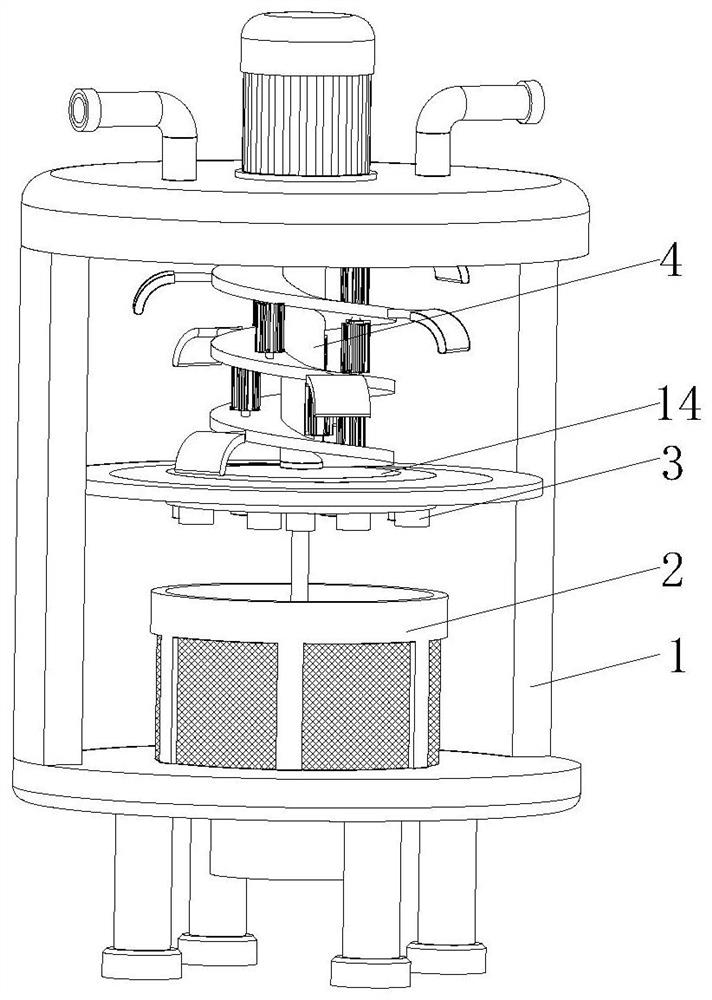
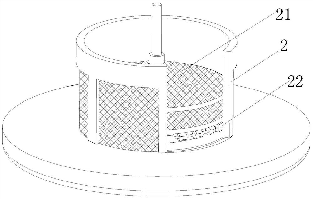
[0028] see Figure 1-8, the present invention provides a technical solution: a chemical reaction purification device, including a reaction cylinder 1, a plurality of support legs are fixedly connected to the bottom of the reaction cylinder 1, and a non-slip base is fixedly connected to the bottom of the support legs, and a The sealing cover 11 is fixedly connected with a pair of liquid inlet pipes 12 on the surface of the sealing cover 11. The liquid inlet pip...


PUM


Abstract

The invention discloses a chemical reaction purification device which comprises a reaction cylinder; a plurality of supporting legs are fixedly connected to the bottom of the reaction cylinder, antiskid bases are fixedly connected to the bottoms of the supporting legs, a sealing cover is fixedly mounted at the top end of the reaction cylinder, a pair of L-shaped liquid inlet pipes are fixedly connected to the surface of the sealing cover, and a driving motor is arranged between the liquid inlet pipes; and the driving motor is fixedly mounted on the surface of the sealing cover, the output end of the driving motor is fixedly connected with a transmission shaft, the inner wall of the reaction cylinder is fixedly connected with a partition plate, and the transmission shaft is rotatably arranged on the surface of the transmission shaft. Compared with the prior art, when chemical raw materials enter from the liquid inlet pipes, the surface of a driving plate can be impacted, the driving plate can deform in the rotating process, the chemical raw materials can be pushed to the outer side in the stirring process, the reaction efficiency of the chemical raw materials is improved, the situation that the chemical raw materials are not fully reacted due to too high feeding speed is avoided, and the waste of the chemical raw materials is reduced.

Description

technical field [0001] The invention relates to the technical field of purification equipment, in particular to a chemical reaction purification device. Background technique [0002] At present, the methods of purifying the liquid after the compounding reaction are nothing more than natural precipitation and mechanical filtration. The former takes a lot of time to allow the internal precipitation to accumulate naturally, and the efficiency is relatively low, and the latter is in the process of filtering the liquid. During the process, the sedimentation is easy to cause the blockage of the screen, and it is easy to accumulate sedimentation on the inner wall of the liquid flow pipe, which will affect the purification efficiency, and the cost of maintaining and cleaning the internal delivery pipe is relatively high. Therefore, we propose a The chemical reaction purification device is used to solve the above problems. Contents of the invention [0003] The purpose of the pres...

Claims


Application Information

Patent Timeline
Patent Type & Authority Applications(China)
IPC IPC(8): B01D36/00B01D33/03B01D33/68B01D33/80B01J19/18
CPCB01D36/003B01D33/0338B01D33/801B01D33/68B01J19/18
Inventor 樊宗波
Owner 樊宗波
Learn More