Static sounding device and static sounding method

It is a technology of static penetrating and penetrating penetrating, which is applied in the survey of foundation soil on site, the test of foundation structure, construction, etc. It can solve the problems of insufficient anchoring force on the surface of soft soil, affecting test results and efficiency, and affecting penetration depth, etc. , to achieve the effect of improving test accuracy and test efficiency, improving penetration efficiency, and avoiding hole inclination or broken rod

Active Publication Date: 2021-12-03
CHINA RAILWAY TIMES BUILDING DESIGIN INST CO LTD
View PDF8 Cites 0 Cited by
  • Summary
  • Abstract
  • Description
  • Claims
  • Application Information

AI Technical Summary

Problems solved by technology

[0006] However, the current static CPT technology also has its disadvantages. For example, the pressurization device of the current static CPT is generally installed on the top of the probe rod above the ground. As a result, the greater the penetration depth, the greater the penetration resistance to be overcome. The self-weight of the machine and the anchoring device need to provide sufficient reaction force. It is very difficult to anchor on the surface of miscellaneous fill or hardened ground, and it will delay time and affect the efficiency. The insufficient anchoring force on the surface of soft soil will affect the penetration depth; When the penetration depth exceeds 30m, or penetrates into the hard soil layer after passing through the thick layer of soft soil, the phenomenon of hole inclination or broken rod is likely to occur, which will affect the test results and efficiency

Method used


Image

  • Static sounding device and static sounding method
  • Static sounding device and static sounding method
  • Static sounding device and static sounding method

Examples


Embodiment Construction

[0032] In order to make the purpose, technical solutions and advantages of the present disclosure clearer, the present disclosure will be further described in detail below in conjunction with specific embodiments.

[0033] It should be noted that, unless otherwise defined, the technical terms or scientific terms used in one or more embodiments of the present specification shall have ordinary meanings understood by those skilled in the art to which the present disclosure belongs. "First", "second" and similar words used in one or more embodiments of the present specification do not indicate any order, quantity or importance, but are only used to distinguish different components. "Comprising" or "comprising" and similar words mean that the elements or items appearing before the word include the elements or items listed after the word and their equivalents, without excluding other elements or items. Words such as "connected" or "connected" are not limited to physical or mechanica...


PUM


Abstract

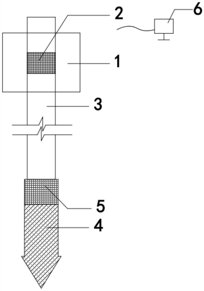
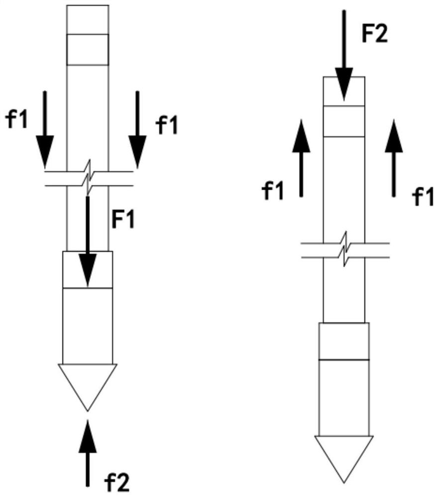
One or more embodiments of the invention provide a static sounding device and a static sounding method. The static sounding device comprises a machine frame, the machine fame is erected on a sounding site, a top pressurizing mechanism is vertically arranged on the machine frame, the top end of a probe rod is connected to the bottom end of the top pressurizing mechanism, a probe head is arranged at the bottom end of the probe rod, and a force transducer is arranged on the probe head; a newly-arranged pressurizing mechanism is connected between the top end of the probe and the probe rod, when a shallow soft soil layer is probed, the top pressurizing mechanism is independently used for pushing the probe rod downwards for a penetration test, and when a deep soil layer or a harder soil layer is probed, in the first step, the newly-arranged pressurizing mechanism is controlled to work to stretch and push the probe at the front end for penetration, and only the end resistance of the probe needs to be overcome; and in the second step, the probe rod is pushed to move downwards through the top pressurizing mechanism, meanwhile, the newly-arranged pressurizing mechanism shrinks and returns, that is, only the side resistance of the soil body around the probe rod needs to be overcome, and the first step and the second step are repeated in this way till the probe penetrates into the designed depth.

Description

technical field [0001] One or more embodiments of this specification relate to the technical field of static penetration testing, and in particular, to a static penetration testing device and a static penetration testing method. Background technique [0002] Static CPT refers to using a pressure device to press a penetrating rod with a contact probe into the test soil layer, and through the measurement system to measure the penetration resistance of the soil, mechanical stratification can be carried out, and the plastic state or compactness and strength of the soil can be estimated. , compressibility, foundation bearing capacity, single pile bearing capacity, etc. There are three types of pressurization methods for static penetration testing: mechanical, hydraulic and human. The static penetration test is carried out on site, and the regression analysis is carried out on the test indicators obtained by the static penetration test and the relevant indicators of the load test...

Claims


Application Information

Patent Timeline
Patent Type & Authority Applications(China)
IPC IPC(8): E02D1/00E02D33/00
CPCE02D1/00E02D33/00
Inventor 汪磊夏京朱敏霍正格
Owner CHINA RAILWAY TIMES BUILDING DESIGIN INST CO LTD
Why Eureka
Try Eureka