Efficient microbubble air dissolving device
A micro-bubble and dissolved gas technology, applied in sustainable biological treatment, flotation water/sewage treatment, etc., can solve the problems affecting the dissolved gas efficiency of the device, cutting effect and limited cutting area, etc., to promote contact with liquid level, reduce Cost of use and effect of improving dissolved gas efficiency
- Summary
- Abstract
- Description
- Claims
- Application Information
AI Technical Summary
Problems solved by technology
Method used
Image
Examples
Embodiment 1
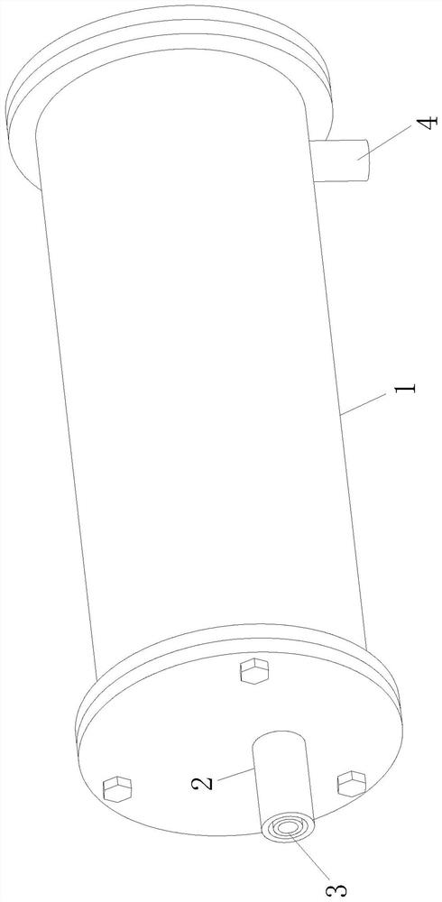
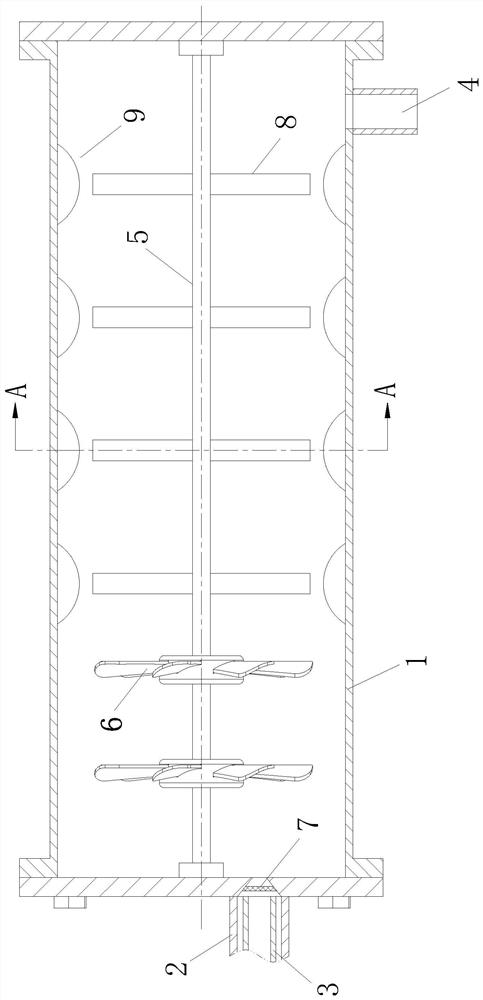
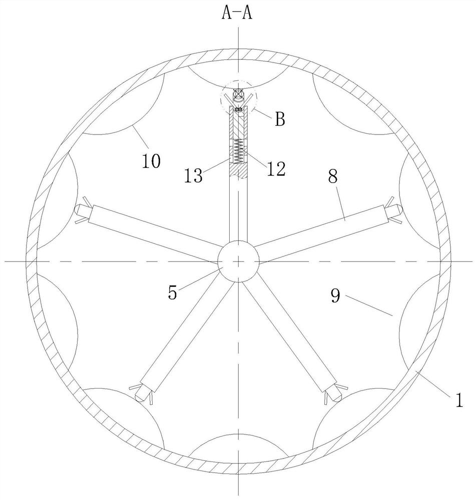
[0029] see Figure 1-4 As shown, a high-efficiency microbubble dissolving device according to the present invention includes a tank body 1; one end of the tank body 1 is provided with a water inlet pipe 2 and an air inlet pipe 3, and the end of the tank body 1 away from the water inlet pipe 2 is arranged There is a water outlet pipe 4, and the middle part of the end face of the tank body 1 is rotatably connected with a rotating rod 5, and the end of the rotating rod 5 close to the water inlet pipe 2 is fixedly connected with a number of spiral fan blades 6; although the existing dissolved air tank body 1 The passing water flow can be cut through the air-dissolving rod 8 on the inner wall, so as to promote the integration of air into the water, but the cutting effect and cutting area of the air-dissolving rod 8 on the water flow are limited, thereby affecting the overall air-dissolving efficiency of the device; and in the present invention When the micro-bubble dissolving dev...
Embodiment 2
[0039] see Figure 5 As shown, the inside of the flow groove 13 is slidably connected with a blocking ball 23, the inner end of the flow groove 13 is connected with a supporting net 24, and an elastic block 25 is connected between the blocking ball 23 and the supporting net 24. Limiting grooves 26 are symmetrically provided on the side walls of the circulation groove 13, and the limiting grooves 26 are internally connected with a limiting plate 27 of elastic material, and the side walls of the limiting grooves 26 can support the free end of the limiting plate 27 away from The rotation of one side of the net 24 is limited; when the slide plate 11 slides to the inside of the sliding cavity, the limit plate 27 limits the movement of the blocking ball 23 to the outer end of the flow groove 13, making it difficult for the liquid inside the sliding cavity to flow out. When the pressure of the sliding plate 11 on the inside of the sliding cavity reaches a certain value, the liquid in...
PUM
 Abstract
Description
Claims
Application Information
 - R&D
- Intellectual Property
- Life Sciences
- Materials
- Tech Scout
- Unparalleled Data Quality
- Higher Quality Content
- 60% Fewer Hallucinations
Browse by: Latest US Patents, China's latest patents, Technical Efficacy Thesaurus, Application Domain, Technology Topic, Popular Technical Reports.
© 2025 PatSnap. All rights reserved.Legal|Privacy policy|Modern Slavery Act Transparency Statement|Sitemap|About US| Contact US: help@patsnap.com


