
Full-automatic numerical control pin corner assembling machine and corner assembling method thereof

A fully automatic and corner forming machine technology, applied in the field of door and window processing equipment, can solve the problems of inability to achieve precise and rapid adjustment of pin position and automatic nailing, restricting the production efficiency and development of pin group corners, etc. The effect of raising the influence and improving the accuracy of the group angle

Pending Publication Date: 2021-12-03
济南康宏机械有限公司
View PDF0 Cites 2 Cited by
  • Summary
  • Abstract
  • Description
  • Claims
  • Application Information

AI Technical Summary

Problems solved by technology

[0003] The principle of pin grouping technology is relatively mature, but there is no mature pin grouping equipment in the market to realize the automatic and precise nailing of pins. The existing pin grouping machines can only realize the mechanization of positioning and clamping of profiles, but cannot realize the position of pins. Accurate and fast adjustment and automatic nailing, the existing technology is still dominated by manual nailing, which seriously restricts the production efficiency and development of pin group corners

Method used


Image

  • Full-automatic numerical control pin corner assembling machine and corner assembling method thereof
  • Full-automatic numerical control pin corner assembling machine and corner assembling method thereof
  • Full-automatic numerical control pin corner assembling machine and corner assembling method thereof

Examples


Embodiment Construction

[0044] In order to explain the overall concept of the present invention more clearly, the following will be described in detail by way of examples in conjunction with the accompanying drawings.

[0045] In the following description, many specific details are set forth in order to fully understand the present invention. However, the present invention can also be implemented in other ways different from those described here. Therefore, the protection scope of the present invention is not limited by the specific details disclosed below. EXAMPLE LIMITATIONS.

[0046] Each embodiment in this specification is described in a progressive manner, the same and similar parts of each embodiment can be referred to each other, and each embodiment focuses on the differences from other embodiments.

[0047] In addition, the terms "transverse", "longitudinal", "front and back", "upper end" and the like are used for descriptive purposes only, and should not be construed as indicating or implyin...


PUM


Abstract

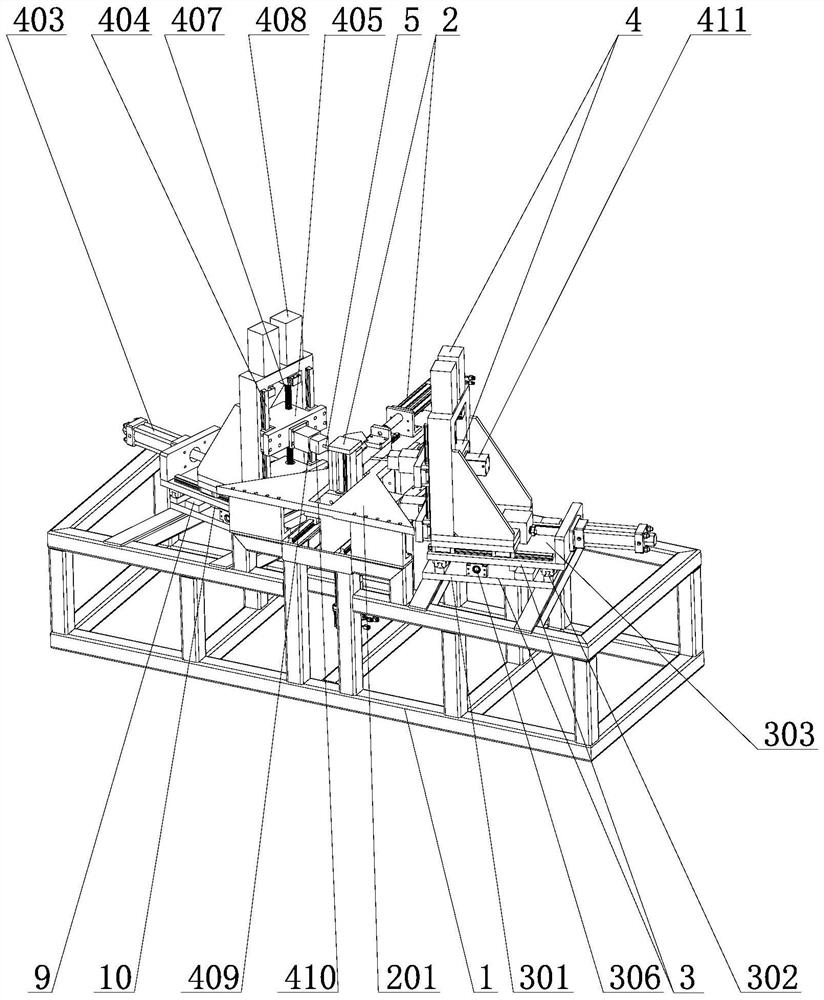
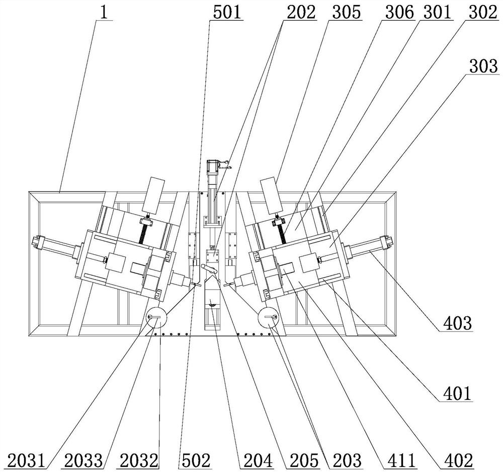
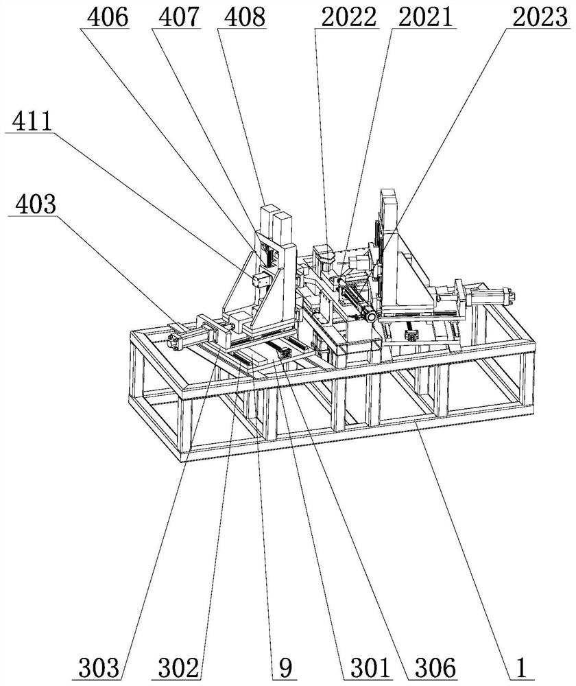
The invention relates to a full-automatic numerical control pin corner assembling machine and a corner assembling method thereof. The full-automatic numerical control pin corner assembling machine comprises a rack, a profile positioning and clamping structure is arranged on the rack, horizontal adjusting mechanisms are arranged on the portions, on the two sides of the profile positioning and clamping structure, of the rack respectively, two-stage pin feeding structures are arranged on the horizontal adjusting mechanisms, and nailing mechanisms are arranged on the two-stage pin feeding structures. A control system is connected with the profile positioning and clamping structure, the horizontal adjusting mechanisms, the two-stage pin feeding structures and the nailing mechanisms. By designing pin corner assembling feeding into two stages, namely, a first-stage feeding oil cylinder is used for adjusting the feeding amount, a second-stage feeding oil cylinder is used for conducting full-stroke feeding, the two-stage feeding scheme can accurately adjust the pin corner assembling feeding amount, and the problem that the pin corner assembling precision is reduced due to the temperature rise of hydraulic oil is solved; and finally, efficient and accurate pin corner assembling is achieved through cooperation with a nailing mechanism. The machine has the advantages of being reasonable in structural design, automatic in nailing, efficient and accurate in nailing position adjustment, accurate in pin feeding amount, capable of achieving double nailing or single nailing and the like.

Description

Technical field: [0001] The invention relates to the technical field of door and window processing equipment, in particular to a full-automatic numerically controlled pin corner-setting machine and a corner-setting method thereof. Background technique: [0002] The corner forming machine is an indispensable processing equipment in door and window processing, and it is mainly used for splicing two adjacent profiles. The existing corner forming machines are mainly divided into two categories: one is to directly impact the profile through the corner forming knife to cause cold deformation of the profile, and then realize the clamping of the corner code and the profile to complete the splicing and fixing of two adjacent profiles . The other is to use the pin installation process. The profile is processed with a round hole, and the corner bracket is provided with a straight groove. When assembling, the corner bracket is inserted into the end of the profile, aligning the ends of ...

Claims


Application Information

Patent Timeline
Patent Type & Authority Applications(China)
IPC IPC(8): B21J15/14B21J15/20B21J15/32B21J15/38
CPCB21J15/14B21J15/20B21J15/32B21J15/38
Inventor 王令红
Owner 济南康宏机械有限公司
Learn More