A backswept disc turbine impeller
A disc turbine stirring and swept-back technology, which is applied to mixers, mixers, dissolving and other directions with rotating stirring devices, can solve the problems of high stirring power consumption and poor mass transfer effect, and achieves enhanced stirring effect, The effect of promoting interphase mass transfer and improving gas-liquid mass transfer performance
- Summary
- Abstract
- Description
- Claims
- Application Information
AI Technical Summary
Problems solved by technology
Method used
Image

Examples
Embodiment 1
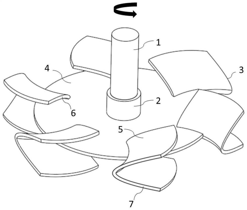
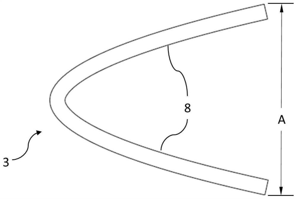
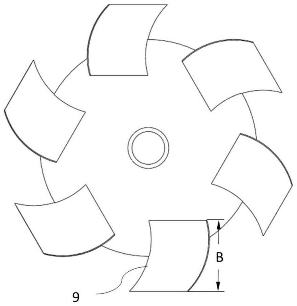
[0046]This embodiment provides a back-swept disc turbine impeller, which includes a disc 4, a paddle 3 and a stirring shaft 1, and the bottom of the stirring shaft 1 is connected to the disc 4 through a hub 2 , the paddle 3 is obtained by extending outward from the radially inner edge 6 along the radial extension line 9 of the paddle to the radially outer edge 7, and the paddle 3 is arranged along the circumference of the disc 4; the paddle The blade 3 is divided into an upper part and a lower part with the horizontal plane where the disc 4 is located; the blade radial extension line 9 at the junction of the upper part and the lower part is a curved structure; the liquid-facing surface 5 of the blade 3 Inwardly recessed and swept back along the radial extension of the blade.
[0047] Two paddles 3 are evenly distributed on the disc 4, the blade radial extension line 9 of the paddle 3 is a parabola, the upper and lower parts of the paddle 3 are symmetrical structures, and the p...
Embodiment 2
[0055] This embodiment provides a back-swept disc turbine impeller, which includes a disc 4, a paddle 3 and a stirring shaft 1, and the bottom of the stirring shaft 1 is connected to the disc 4 through a hub 2 , the paddle 3 is obtained by extending outward from the radially inner edge 6 along the radial extension line 9 of the paddle to the radially outer edge 7, and the paddle 3 is arranged along the circumference of the disc 4; the paddle The blade 3 is divided into an upper part and a lower part with the horizontal plane where the disc 4 is located; the blade radial extension line 9 at the junction of the upper part and the lower part is a curved structure; the liquid-facing surface 5 of the blade 3 Inwardly recessed and swept back along the radial extension of the blade.
[0056] 10 paddles 3 are evenly distributed on the disc 4, the blade radial extension line 9 of the paddle 3 is an elliptical arc, the upper and lower parts of the paddle 3 are symmetrical structures, an...
Embodiment 3
[0064] This embodiment provides a back-swept disc turbine impeller, which includes a disc 4, a paddle 3 and a stirring shaft 1, and the bottom of the stirring shaft 1 is connected to the disc 4 through a hub 2 , the paddle 3 is obtained by extending outward from the radially inner edge 6 along the radial extension line 9 of the paddle to the radially outer edge 7, and the paddle 3 is arranged along the circumference of the disc 4; the paddle The blade 3 is divided into an upper part and a lower part with the horizontal plane where the disc 4 is located; the blade radial extension line 9 at the junction of the upper part and the lower part is a curved structure; the liquid-facing surface 5 of the blade 3 Inwardly recessed and swept back along the radial extension of the blade.
[0065] Six paddles 3 are uniformly distributed on the disc 4, the blade radial extension line 9 of the paddle 3 is a circular arc, the upper and lower parts of the paddle 3 are symmetrical structures, a...
PUM
 Abstract
Description
Claims
Application Information
 - Generate Ideas
- Intellectual Property
- Life Sciences
- Materials
- Tech Scout
- Unparalleled Data Quality
- Higher Quality Content
- 60% Fewer Hallucinations
Browse by: Latest US Patents, China's latest patents, Technical Efficacy Thesaurus, Application Domain, Technology Topic, Popular Technical Reports.
© 2025 PatSnap. All rights reserved.Legal|Privacy policy|Modern Slavery Act Transparency Statement|Sitemap|About US| Contact US: help@patsnap.com