Transmission structure, transmission connection mechanism and air compressor
A technology of transmission structure and driving mechanism, which is applied in the field of mechanical transmission, can solve problems such as low transmission efficiency, large loss, and low work efficiency, and achieve the effects of improving transmission efficiency, long mission life, and increasing work efficiency
- Summary
- Abstract
- Description
- Claims
- Application Information
AI Technical Summary
Problems solved by technology
Method used
Image
Examples
Embodiment 1
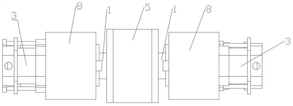
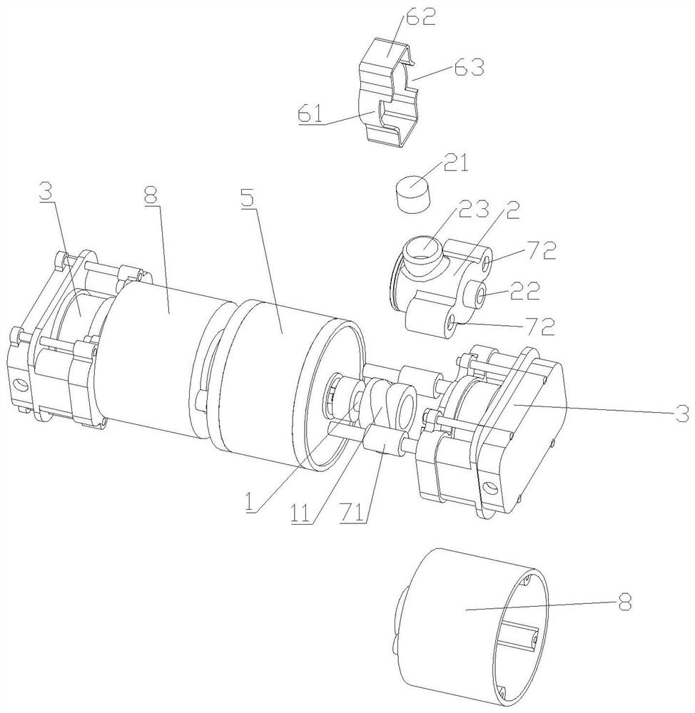
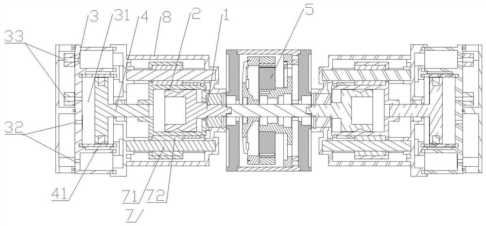
[0033] combined with Figure 1-6 , the transmission structure of this embodiment includes a rotating shaft 1 and a transmission body 2, one end of the rotating shaft 1 is provided with a limit track 11, the other end of the rotating shaft 1 is used to connect the driving mechanism 5, and one end of the transmission body 2 is movable with the limit track 11 Cooperate so that when the rotating shaft 1 rotates, the transmission body 2 reciprocates along the axis of the rotating shaft 1 under the limit of the limit track 11, and the other end of the transmission body 2 is used to connect the equipment that needs linear reciprocating work. The driving mechanism 5 drives the rotating shaft 1 to rotate. When the rotating shaft 1 rotates, the transmission body 2 reciprocates along the axis of the rotating shaft 1 under the limit of the limit track 11, so that the equipment connected to the transmission body 2 reciprocates along a straight line to do work, which is beneficial Reduce de...
Embodiment 2
[0035] combined with Figure 1-6 , the transmission structure of this embodiment, compared with the technical solution of Embodiment 1, can be improved as follows: one end of the transmission body 2 is symmetrically provided with a transmission member 21, and the limiting track 11 extends along the circumferential direction of the rotating shaft 1, and The limiting track 11 is reciprocally extended along the axial direction of the rotating shaft 1 , and the transmission member 21 is movably matched with the limiting track 11 . When the rotating shaft 1 rotates, the symmetrical arrangement enables the transmission members 21 to cancel each other's biasing forces, thereby driving the transmission body 2 to reciprocate along the axis of the rotating shaft 1 . There can be many pairs of transmission parts 21, and there can be many limit tracks 11 that are movably matched with the transmission parts 21. When there are many limit tracks 11, the multiple limit tracks 11 are divided i...
Embodiment 3
[0039] combined with Figure 1-6 , the transmission structure of this embodiment, compared with the technical solution of embodiment 1 or 2, can be improved as follows: the transmission body 2 has a cavity 31 for the shaft 1 to pass through and a channel 23 for placing the transmission member 21, the The channel 23 is in communication with the cavity 31 , the transmission member 21 is closely fitted with the channel 23 , and the top of the channel 23 is covered with the fastener 6 . The fastener 6 securely fixes the transmission part 21 in the channel 23 to ensure that the transmission part 21 drives the transmission body 2 to perform reciprocating linear motion. The fastener 6 includes a hoop body 61 and a pressure plate 62 connected to the hoop body 61 , the hoop body 61 is sheathed on the outer surface of the transmission body 2 , and the pressure plate 62 covers the top of the channel 23 . The hoop body 61 and the pressing plate 62 are integrally formed to provide a bette...
PUM
 Abstract
Description
Claims
Application Information
 - R&D
- Intellectual Property
- Life Sciences
- Materials
- Tech Scout
- Unparalleled Data Quality
- Higher Quality Content
- 60% Fewer Hallucinations
Browse by: Latest US Patents, China's latest patents, Technical Efficacy Thesaurus, Application Domain, Technology Topic, Popular Technical Reports.
© 2025 PatSnap. All rights reserved.Legal|Privacy policy|Modern Slavery Act Transparency Statement|Sitemap|About US| Contact US: help@patsnap.com


