
Sudden-expansion drop sill stilling basin suitable for high water head and large single-width discharge capacity

A technology of sudden expansion of falling sills and stilling pools, applied in water conservancy projects, marine engineering, construction, etc., can solve the problems of stilling pool overflow surface scouring, increase project investment, large flood discharge power, etc., and achieve flow-induced vibration. Small, save project investment, increase the effect of energy dissipation rate

Active Publication Date: 2021-11-30
POWER CHINA KUNMING ENG CORP LTD +1
View PDF9 Cites 0 Cited by
  • Summary
  • Abstract
  • Description
  • Claims
  • Application Information

AI Technical Summary

Problems solved by technology

Due to the high velocity of flow into the pond and the high power of flood discharge, the energy dissipation of the large discharge volume and high water head may cause serious erosion to the flow surface of the stilling basin. The flow-induced vibration can lead to structural instability and foundation erosion
Generally speaking, the stilling basin can be prevented from being damaged by extending the length of the stilling basin, increasing the width of the stilling basin and the depth of the water cushion, and increasing the thickness of the concrete lining, but the above method increases the project investment

Method used


Image

  • Sudden-expansion drop sill stilling basin suitable for high water head and large single-width discharge capacity
  • Sudden-expansion drop sill stilling basin suitable for high water head and large single-width discharge capacity
  • Sudden-expansion drop sill stilling basin suitable for high water head and large single-width discharge capacity

Examples


Embodiment

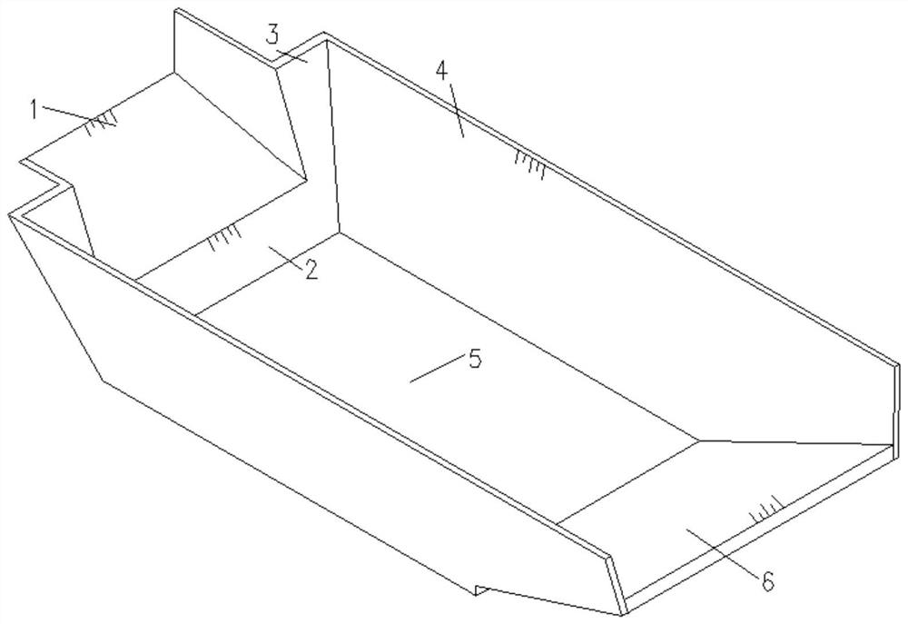
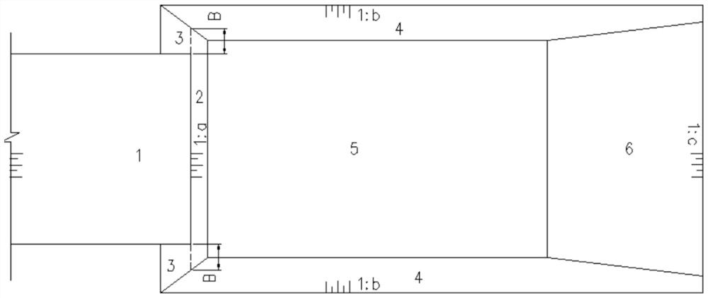
[0041] A hydropower station adopts the sudden expansion of the stilling pool of the sill with this structure. 4 side walls of the force pool, 5 bottom plates of the stilling pool, and 6 end sills.

[0042] Among them, the height of the bottom sill 2 should not be less than 8m,

[0043] The width of sudden expansion 3 on both sides should not be less than 10m from the same horizontal plane as the discharge chute.

[0044] The slope of the bottom drop 2 and the sudden expansion 3 is 1:0~1:0.4,

[0045] The height of the tail sill 6 is 1.1 to 1.3 times the water depth of the head of the stilling pool corresponding to the jumping head occurring at the end of the sill.

[0046] Preferably, the height of the falling ridge 2 is 15.7m, the width B of the sudden expansion 3 is 10m, and the height of the tail sill 6 is 1.2 times of the upstream water depth of the stilling pool corresponding to the upstream water level of the jumping head that occurs at the end of the jumping ridge 1 a...


PUM


Abstract

The invention relates to a sudden-expansion drop sill stilling basin suitable for a high water head and a large single-width discharge capacity. The sudden-expansion drop sill stilling basin comprises a flip sill, a bottom drop sill, sudden expansions, side walls, a bottom plate and tail sills. The sudden-expansion drop sill stilling basin is arranged at the downstream of a spillway discharge chute; the bottom drop sill is arranged at the lower part of the flip sill; two sides of the bottom drop sill are connected with the lower parts of the side walls; the sudden expansions are connected to the upper parts of the two sides of the bottom drop sill and the middle parts and the upper parts of the side walls; the side walls are symmetrically arranged; the tail sills are arranged at the tail ends of the symmetrically arranged side walls, and the two sides of the tail sills are connected with the side edges of the tail ends of the side walls; the flip sill is provided with a certain depression angle. According to the sudden-expansion drop sill stilling basin suitable for the high water head and the large single-width discharge capacity, the hydraulic index near the bottom of the stilling basin can be remarkably reduced, the energy dissipation rate is increased, and the safety performance of a water drainage and energy dissipation building which is high in water head and large in single-width discharge capacity and has strict requirements for atomization can be improved.

Description

technical field [0001] The invention belongs to the technical field of water conservancy and hydropower engineering, and in particular relates to the technical field of structural parameters and a design method of a suddenly expanding sill stilling pool suitable for high water head, large unit and wide discharge capacity. Background technique [0002] In water conservancy and hydropower projects, the stilling pool is a commonly used energy dissipation device. Compared with surface flow and deflected flow energy dissipation, it has the characteristics of stable shape, good energy dissipation effect, and small atomization. However, due to the high mainstream flow velocity at the bottom, it is often necessary to line the riverbed within a certain length downstream and form a stilling basin to control the discharge water body and prevent destructive erosion, which requires a large amount of engineering. Generally, common stilling basins include down-dug stilling basins, sill-typ...

Claims


Application Information

Patent Timeline
Patent Type & Authority Applications(China)
IPC IPC(8): E02B8/06
CPCE02B8/06Y02E10/20
Inventor 杨再宏杨吉健刘绍川练继建李会平
Owner POWER CHINA KUNMING ENG CORP LTD
Learn More