Collision combined underflow energy dissipator structure
An energy dissipation and overflow technology for undercurrents, applied in water conservancy projects, marine engineering, coastline protection, etc. It can solve the problems of complex layout, impact damage, and great threat to dam sites, avoiding vertical axis vortex damage and reducing water flow pulsation. , the effect of improving energy dissipation efficiency
- Summary
- Abstract
- Description
- Claims
- Application Information
AI Technical Summary
Problems solved by technology
Method used
Image
Examples
Embodiment 1
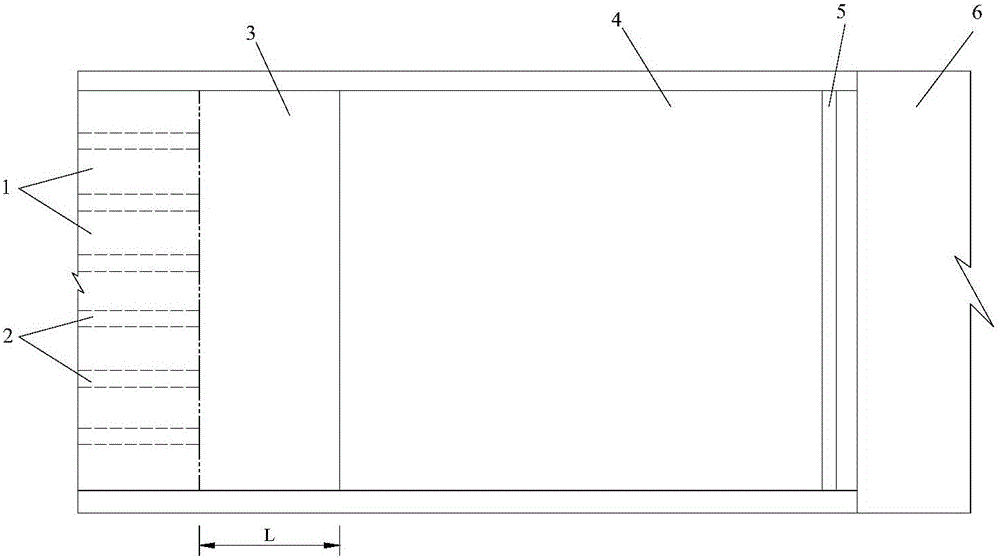
[0061] Embodiment 1 and Embodiment 2 respectively represent two different forms of continuous type and interval type for the structure of the secondary discharge trough, and in each case, the end ridge is divided into two types: continuous type and differential type.
[0062] The continuous end ridge means that the end of the ridge of the secondary discharge groove is a continuous smooth overflow surface.
[0063] The differential end ridge refers to the overflow surface with the same height difference at the end of the ridge of the secondary discharge groove perpendicular to the direction of water flow. The embodiment is applicable to two forms of continuous outflow and multi-strand outflow of the upstream first-stage discharge groove. When the chute partition wall is not included, the upstream first-stage chute adopts a continuous discharge method, and the jet produced is a continuous jet; For multiple jets.
[0064] The collision-type combined underflow energy dissipator ...
Embodiment 2
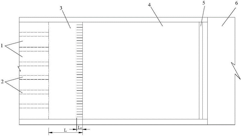
[0075] Such as image 3 and Figure 4 Shown is a schematic plan view and a schematic elevation view of the second embodiment of the present invention.
[0076] The structure of the collision-type combined underflow energy dissipator in this embodiment includes a first-stage discharge trough 1, a chute partition wall 2, a secondary discharge trough 3, a stilling pool 4, a stilling pool tail sill 5 and a downstream guard. Tank 6.
[0077] Among them, the end of the primary discharge tank 1 is horizontal, and there is a certain elevation difference with the bottom plate of the stilling tank 4; The overflow surface is a continuous smooth surface, and the discharge water flow is continuously concentrated into the pool; the overflow surface of the secondary discharge groove 3 is smoothly connected with the end of the primary discharge groove 1, and the length L of the secondary discharge groove is taken as 2P~ 3P, P are the heights from the end of the primary discharge tank 1 to ...
Embodiment 3
[0081] Such as Figure 5 and Image 6 Shown is a schematic plan view and a schematic elevation view of the third embodiment of the present invention.
[0082] The new combined underflow energy dissipator structure in this embodiment consists of a first-stage discharge trough 1, a chute partition wall 2, a secondary discharge trough 3, a stilling tank 4, a stilling tank tail sill 5 and a downstream apron 6.
[0083] Among them, the end of the first-stage discharge groove 1 is horizontal, and there is a certain elevation difference with the bottom plate of the stilling pool 4; the second-stage discharge groove 3 is of an interval type, and the discharge water flow is divided into multiple jets scattered into the pool; the second-stage discharge groove 3 The curved surface of the overflow is smoothly connected to the end of the primary discharge tank 1, the length L is 2P to 3P, and P is the height from the end of the primary discharge tank 1 to the bottom plate of the stilling...
PUM
 Abstract
Description
Claims
Application Information
 - Generate Ideas
- Intellectual Property
- Life Sciences
- Materials
- Tech Scout
- Unparalleled Data Quality
- Higher Quality Content
- 60% Fewer Hallucinations
Browse by: Latest US Patents, China's latest patents, Technical Efficacy Thesaurus, Application Domain, Technology Topic, Popular Technical Reports.
© 2025 PatSnap. All rights reserved.Legal|Privacy policy|Modern Slavery Act Transparency Statement|Sitemap|About US| Contact US: help@patsnap.com


