Combined energy dissipation structure and energy dissipation method of overflow weir and elastic stilling basin
A technology for stilling tanks and overflow weirs, applied in barrage/weirs, sea area engineering, construction, etc., can solve the problems of low energy dissipation efficiency of stilling tanks and excessive pressure on the bottom plate of stilling tanks, and improve fog phenomenon, reduce dynamic water pressure, and have obvious effects of energy dissipation
- Summary
- Abstract
- Description
- Claims
- Application Information
AI Technical Summary
Problems solved by technology
Method used
Image
Examples
Embodiment 1
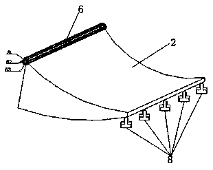
[0038] Embodiment 1: as Figure 1~12 As shown, the combined energy dissipation structure of the overflow weir and the elastic stilling tank includes the overflow weir and the stilling tank. The overflow weir includes a WES straight section 1 and a WES reverse arc section 2. The WES straight section 1 It is connected with the WES anti-arc section 2, and a rotating shaft component 6 is provided at the connection. The bottom of the tail of the WES anti-arc section 2 is provided with a hydraulic jacking device 8, and the tail of the overflow weir WES anti-arc section 2 Connected with the stilling pool, the stilling pool includes the head part 3 of the stilling pool, the middle part 4 of the stilling pool and the tail part 5 of the stilling pool. 3 connection, the bottom of the stilling pool is installed with rubber bearings according to the pressure it bears, because the pressure on the head 3 of the stilling pool is relatively large, which is about 1.5 times that of the middle pa...
Embodiment 2
[0045] Embodiment 2: The structure of this embodiment is the same as that of Embodiment 1. The difference is that rubber bearings are installed at the bottom of the stilling pool according to the pressure it bears. 1.5 times that of the middle part 4 of the stilling pool, so the density of rubber bearings under the bottom plate of the head 3 of the stilling pool is 25㎡ / piece; while the pressure on the middle part 4 of the stilling pool is about 1.3 of the pressure at the tail 5 of the stilling pool times, so the density of the rubber bearings under the bottom plate is 37.5㎡ / piece; for the pressure at the end 5 of the stilling pool, the density of the rubber bearings under the bottom plate of the stilling pool’s tail 5 is 50㎡ / time, the effect achieved is ideal.
[0046] This embodiment is mainly used for single-width flow at 170m 3 / s·m~195m 3 / s·m for energy dissipation, adjust the hydraulic pump 8-1 of the hydraulic jacking device 8 to lower the hydraulic pump 8-1, thereb...
Embodiment 3
[0048] Embodiment 3: The structure of this embodiment is the same as that of Embodiment 1. The difference is that rubber bearings are installed at the bottom of the stilling tank according to the pressure it bears. In this embodiment, the overall pressure of the stilling tank generally increases , so the density of the overall rubber support of the stilling pool should be increased accordingly. Because the pressure on the head 3 of the stilling pool is relatively large, which is about 1.5 times that of the middle part 4 of the stilling pool, so for the head 3 of the stilling pool The density of rubber bearings under the bottom plate is 30㎡ / piece; while the pressure in the middle part 4 of the stilling pool is about 1.3 times the pressure at the end of the stilling pool 5, so the density of rubber bearings under the bottom plate is 45㎡ / piece; for the pressure borne by the tail part 5 of the stilling pool, when the density of rubber bearings installed under the bottom plate of ...
PUM
 Abstract
Description
Claims
Application Information
 - R&D
- Intellectual Property
- Life Sciences
- Materials
- Tech Scout
- Unparalleled Data Quality
- Higher Quality Content
- 60% Fewer Hallucinations
Browse by: Latest US Patents, China's latest patents, Technical Efficacy Thesaurus, Application Domain, Technology Topic, Popular Technical Reports.
© 2025 PatSnap. All rights reserved.Legal|Privacy policy|Modern Slavery Act Transparency Statement|Sitemap|About US| Contact US: help@patsnap.com


