Biological environment-friendly expansion-drop combination energy dissipater

An eco-environment-friendly technology, applied in water conservancy projects, sea area projects, coastline protection, etc., can solve the problems that the bottom plate is threatened by the vertical shaft vortex, shorten the length of the stilling pool, etc., to improve the downstream ecological environment, the atomization range is small, Reduce the effect of twirling

Active Publication Date: 2014-12-17
CHINA THREE GORGES CORPORATION
View PDF9 Cites 0 Cited by
  • Summary
  • Abstract
  • Description
  • Claims
  • Application Information

AI Technical Summary

Problems solved by technology

[0006] The purpose of the present invention is to solve the contradiction between energy dissipation efficiency and the ecological environment. Aiming at the defects in the prior art, an eco-environment-friendly drop-expansion combined energy dissipation device suitable for large-scale water conservancy projects is proposed. The energy dissipation concept is applied to the underflow energy dissipator, which not only solves the problem that the bottom plate of the downstream stilling pool is threatened by the vertical axis vortex under the large flow rate, but also reduces the gas supersaturation under the premise of improving the energy dissipation efficiency of the underflow energy dissipator degree, reducing the impact on the downstream ecological environment; at the same time, the length of the stilling pool can be shortened, thereby saving the project cost

Method used


Image

  • Biological environment-friendly expansion-drop combination energy dissipater
  • Biological environment-friendly expansion-drop combination energy dissipater
  • Biological environment-friendly expansion-drop combination energy dissipater

Examples


Embodiment 1

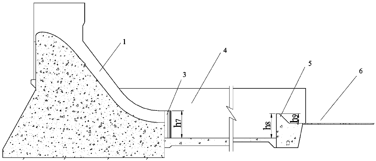
[0044] The structure of the eco-environmentally friendly drop-expansion combined energy dissipator in this embodiment is as follows: figure 1 , figure 2 , Figure 5 , Figure 9 , Figure 11 with Figure 13 As shown, its structural composition includes seven high sill discharge troughs 1, seven low sill sill discharge troughs 2, solid water carrying sills 10, seven chute partition walls 7, stilling pools 4, and stilling pool tail sills 5 , Downstream apron 6. It should be noted that the number of the above-mentioned high sill drain grooves and low sill drain grooves is only exemplary, and should not be construed as limiting, and the number can be two, three or any number.

[0045] Among them: the high sill discharge tank 1 is a non-pressurized horizontal outflow in the form of splits, such as Figure 5 shown; each drain slot 1 width d 2 = 12m, the thickness of the chute partition wall is 7 d 3 = 4m. The low-sill discharge trough and the high-sill discharge trough are ...

Embodiment 2

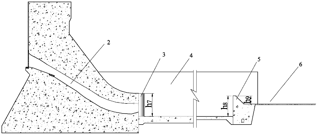
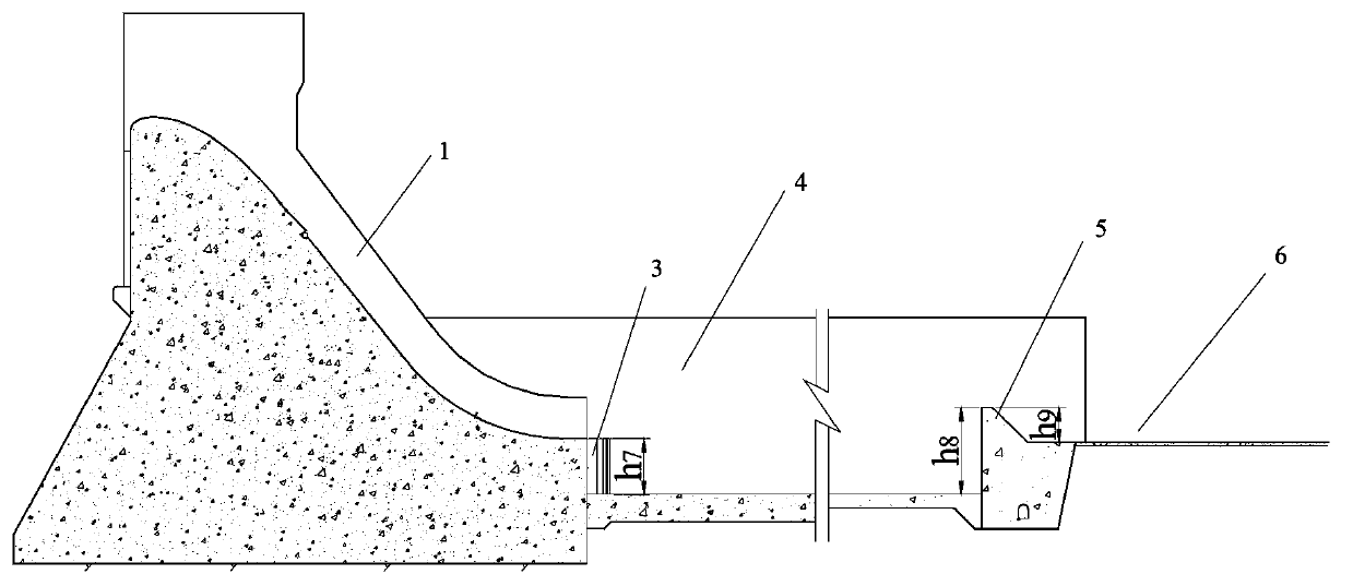
[0047] The structure of the eco-environmentally friendly drop-expansion combined energy dissipator in this embodiment is as follows: figure 1 , figure 2 , Image 6 , Figure 9 , Figure 11 with Figure 13 As shown, the structural composition includes seven high sill discharge troughs 1, seven low sill sill discharge troughs 2, solid water carrying sills 10, seven chute partition walls 7, stilling pools 4, stilling pool tail sills 5, Downstream armor 6. Among them: the high-sill discharge trough is in the form of splits without pressure outflow, and the outlet of the high-sill discharge trough is set at a depression angle of 1:10 from the end of the overflow dam surface, as shown in Image 6 Shown; each high sill 1 width d 2 = 12m, the thickness of the chute partition wall is 7 d 3 =4m, 1:10 depression angle section 9 length L 6 = 8m. The low-sill discharge trough and the high-sill discharge trough are arranged in parallel in the same way, and they are pressurized mul...

Embodiment 3

[0049] The structure of the eco-environment friendly drop-diffusion bottom flow energy dissipator in this embodiment is as follows: figure 1 , figure 2 , Figure 5 , Figure 10 , Figure 11 , Figure 14 with Figure 15 As shown, the structural composition includes seven high sill discharge troughs 1, seven low sill sill discharge troughs 2, tooth grid type water carrying sills 11, seven chute partition walls 7, stilling pool 4, and stilling pool tail sill 5 , Downstream apron 6. Among them: the high sill discharge trough is a non-pressurized horizontal outflow in the form of splits, such as Figure 5 Shown; each high sill 1 width d 2 = 12m, the thickness of the chute partition wall is 7 d 3 = 4m. The low sill discharge trough 2 and the high sill discharge trough 1 are arranged in parallel in the same arrangement, both of which are pressurized and multi-strand outflows, such as Figure 10 As shown, each low sill chute is 2 wide d 1 = 12m, the thickness of the chute ...


PUM


Abstract

The invention belongs to a flood discharge energy dissipation facility, and discloses a biological environment-friendly expansion-drop combination energy dissipater. The energy dissipater comprises a plurality of upstream flood discharge slots, flood discharge partition walls arranged among the upstream flood discharge slots, a flow picking structure arranged at the tail ends of the upstream flood discharge slots, a stilling basin arranged at the downstream of the flow picking structure, and a stilling basin tail weir and a downstream apron arranged at the downstream of the stilling basin, wherein the upstream flood discharging slots consist of a plurality of high-weir flood discharge slots and a plurality of low-weir flood discharge slots; and the high-weir flood discharge slots and the low-weir flood discharge slots are arranged in parallel from top to bottom. According to energy dissipater provided by the invention, the problem that the bottom plate of multi-strand flood discharge downstream stilling basin is suffered from the threat of vertical vortex under large flow; and moreover, under the promise that the energy dissipation efficiency of the bottom flow energy dissipater is improved, the gas super-saturation is reduced, and the influence to the downstream biological environment is reduced.

Description

technical field [0001] The invention belongs to flood discharge and energy dissipation facilities, in particular to an eco-environmentally friendly energy dissipation combined drop-expansion facility suitable for large-scale water conservancy projects. Background technique [0002] Environmental protection has become the basic requirement for the development of water conservancy and hydropower projects in today's society, and the development of environmentally friendly planning, design and operation management is an inevitable trend in the development of water conservancy science and technology in the future. Flood discharge and energy dissipation is one of the important components of hydraulic engineering planning and design. In the process of flood discharge and power generation discharge of water conservancy and hydropower projects, the discharge water flow undergoes strong turbulence and aeration, which makes the content of dissolved gas in the downstream channel signifi...

Claims


Application Information

Patent Timeline
Patent Type & Authority Patents(China)
IPC IPC(8): E02B8/06
Inventor 戴会超郑铁刚柳海涛
Owner CHINA THREE GORGES CORPORATION
Why Eureka
Try Eureka