Sulfur autotrophic denitrification advanced denitrogenation process and device
A deep denitrification, sulfur autotrophic technology, applied in aerobic and anaerobic process treatment, chemical instruments and methods, special compound water treatment, etc., to improve activity and sulfate reduction efficiency, reduce floor space, and reduce costs Effect
Pending Publication Date: 2021-11-30
HEBEI UNIVERSITY OF SCIENCE AND TECHNOLOGY
View PDF9 Cites 2 Cited by
- Summary
- Abstract
- Description
- Claims
- Application Information
AI Technical Summary
Problems solved by technology
[0004] At present, in our country, there are many processes that are rich in high COD (chemical oxygen demand, reflecting the content of reducing substances in water), high SO 4 2- C/N/S in wastewater can be removed at the same time, an
Method used
View moreImage
Smart ImageViewing Examples

Examples
 PUM
 Abstract
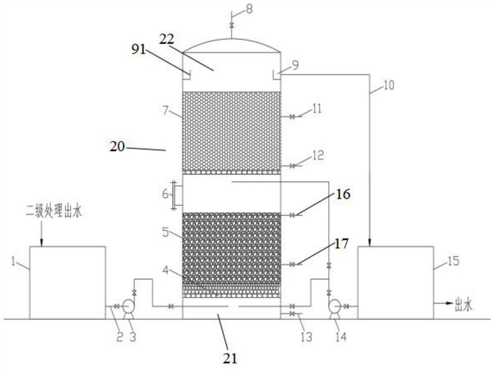
The invention relates to a sulfur autotrophic denitrification advanced denitrogenation device using sulfate in water as a sulfur source. The device comprises a filter tower. Secondary effluent to be treated enters from the lower part of the filter tower, and is treated and then discharged from the upper part of the filter tower. The filter tower is also provided with an exhaust port. The filter tower comprises a sulfate reduction area located at the lower part and a sulfur autotrophic denitrification area located at the upper part. A solid slow-release carbon source feeding hole is formed between the sulfate reduction area and the sulfur autotrophic denitrification area, and a slow-release carbon source can be supplemented to the sulfate reduction area through the solid slow-release carbon source feeding hole. The sulfate reduction area is filled with a filter material, and a sulfate reducing bacteria biological membrane is hung on the filter material. The sulfur autotrophic denitrification area is filled with a filter material, and a sulfur autotrophic denitrifying bacterium biological membrane is hung on the filter material. According to the invention, with sulfate contained in wastewater as an indirect nutrition source, sulfur autotrophic denitrification advanced denitrogenation is carried out under the condition of no additional sulfur source, so that resources are saved, the utilization rate of the sulfur source is maximized, and the operation cost is reduced. The process and the device are especially suitable for treating secondary effluent with low C/N ratio.
Description
technical field [0001] The invention relates to the technical field of wastewater denitrification, in particular to a sulfur autotrophic denitrification deep denitrification process and device using sulfate in water as a sulfur source. Background technique [0002] Denitrification, as the key process of wastewater denitrification, has always been an important technology for wastewater treatment. At present, most of the sewage treatment adopts traditional heterotrophic denitrification technology and process. Traditional denitrification uses heterotrophic facultative anaerobic bacteria in an environment with extremely low dissolved oxygen, using nitrate as the electron acceptor and organic matter as the electron acceptor. Donor and provide energy to reduce nitrate to N 2 In the process of treating low C / N wastewater, it is necessary to continuously add carbon sources to the wastewater, which will greatly increase the operating cost and cause the risk of secondary pollution. ...
Claims
Login to View More Application Information
Patent Timeline
 IPC IPC(8): C02F3/30C02F3/34C02F101/10C02F101/16
CPCC02F3/345C02F3/302C02F2305/06C02F2003/001C02F2101/101C02F1/66C02F2209/06C02F2209/02C02F2209/44C02F2303/16C02F2303/14C02F2209/08C02F2209/15C02F2209/10C02F2101/163
Inventor 李再兴尹思婕刘晓帅刘艳芳秦学马骏
Owner HEBEI UNIVERSITY OF SCIENCE AND TECHNOLOGY
Features
- R&D
- Intellectual Property
- Life Sciences
- Materials
- Tech Scout
- Unparalleled Data Quality
- Higher Quality Content
- 60% Fewer Hallucinations
Learn More Browse by: Latest US Patents, China's latest patents, Technical Efficacy Thesaurus, Application Domain, Technology Topic, Popular Technical Reports.
© 2025 PatSnap. All rights reserved.Legal|Privacy policy|Modern Slavery Act Transparency Statement|Sitemap|About US| Contact US: help@patsnap.com