
BIM-based digital engineering monitoring system

A monitoring system and engineering technology, which can be applied to the components of TV systems, chemical instruments and methods, and components of color TVs, etc. Effect

Active Publication Date: 2021-11-26
浙江新和兴建设有限公司
View PDF5 Cites 2 Cited by
  • Summary
  • Abstract
  • Description
  • Claims
  • Application Information

AI Technical Summary

Problems solved by technology

[0005] In order to improve the problem that the monitoring picture of the monitoring camera is not clear due to water mist, this application provides a BIM digital engineering monitoring system

Method used


Image

  • BIM-based digital engineering monitoring system
  • BIM-based digital engineering monitoring system
  • BIM-based digital engineering monitoring system

Examples


Embodiment Construction

[0043] The following is attached Figure 1-7 The application is described in further detail.

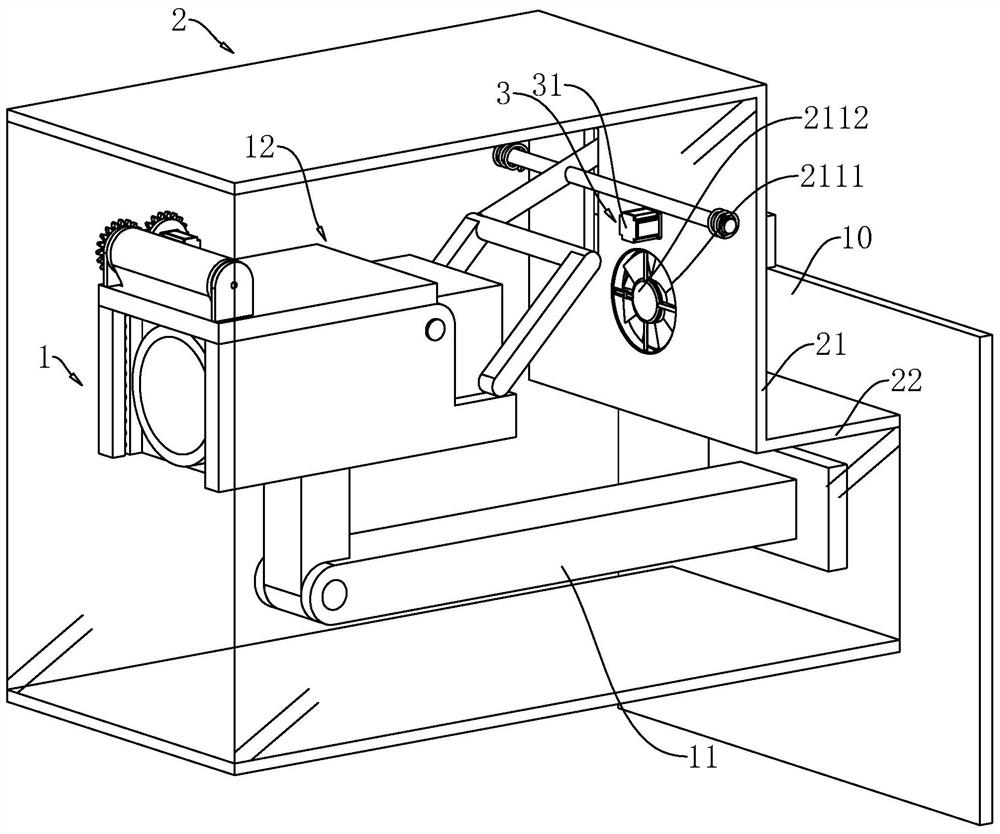
[0044] The embodiment of the present application discloses a BIM digital engineering monitoring system. refer to figure 1 , the BIM digital engineering monitoring system includes a monitoring camera body 1 and a protective cover 2 for accommodating the monitoring camera body 1 . The protective cover 2 includes a main cover 21 and a secondary cover 22 . The secondary cover 22 is used for fixing to the wall 10 . Surveillance camera body 1 comprises the camera main body 11 that is used to fix with wall 10 and is fixed on the camera lens 12 of camera main body 11 away from wall 10 one end, and camera main body 11 is positioned at secondary cover 22, and camera lens 12 is positioned at main cover 21, And the mirror surface of the camera lens 12 faces the side away from the wall 10 .

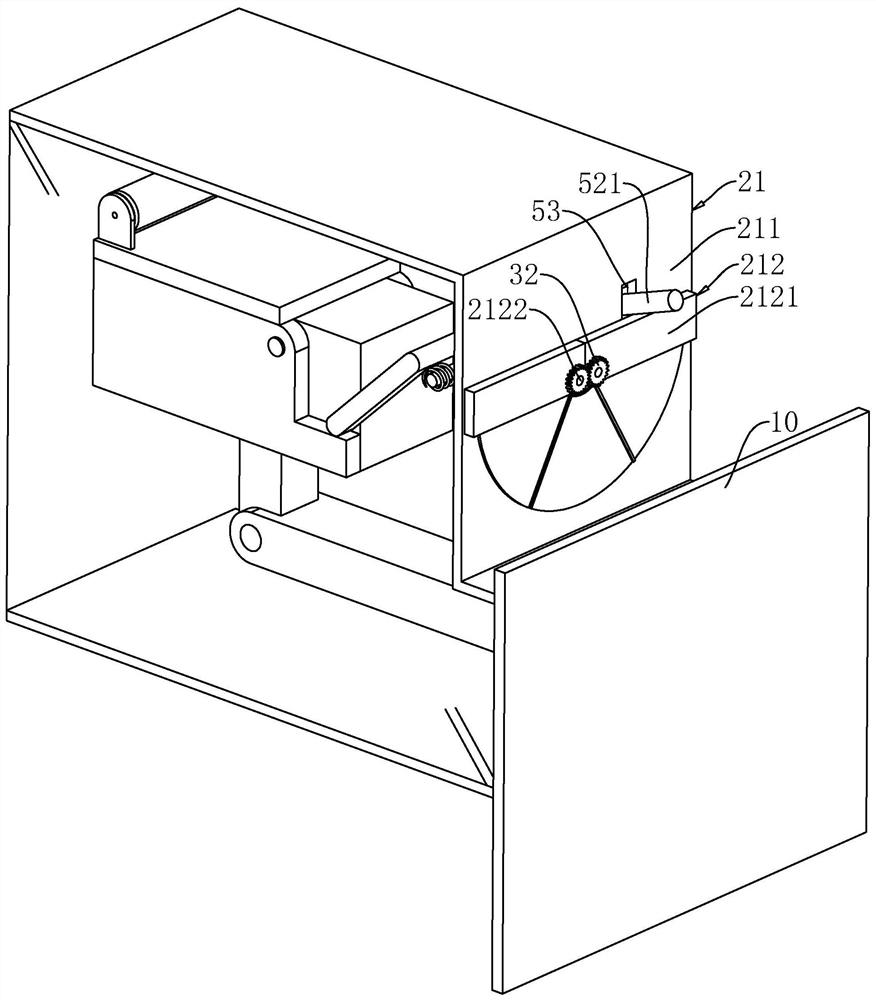
[0045] refer to figure 1 , figure 2 The main cover 21 includes an outer cover 211 and a cover plat...


PUM


Abstract

The invention relates to a BIM-based digital engineering monitoring system, which comprises a monitoring camera body and a protective cover for accommodating the monitoring camera, and is characterized in that the protective cover comprises a main cover and a secondary cover which are communicated with each other, the secondary cover is used for being fixed with a wall surface, and one end, far away from the wall surface, of the secondary cover is communicated with the side wall of the bottom end of the main cover; the main cover comprises an outer cover and a cover plate, a through opening is formed in the side wall, facing the wall surface, of the top end of the outer cover, and the cover plate is used for closing the through opening; the driving source is arranged on the outer cover and used for driving the cover plate to move and then opening the through opening; the exhaust fan is arranged on the outer cover and is used for driving air in the protective cover to flow out of the through hole; and the humidity sensor and the central processing unit are arranged in the protective cover, and the central processing unit is electrically connected with the humidity sensor, the driving source and the exhaust fan. The exhaust fan exchanges air in the protective cover with the outside, so that the humidity in the protective cover is consistent with that of the outside, the inner wall of the protective cover is not easy to be covered with fog water, and the monitoring picture of the camera is kept clear.

Description

technical field [0001] This application relates to the technical field of monitoring systems, in particular to BIM digital engineering monitoring systems. Background technique [0002] The method of virtual layout of monitoring cameras on construction site can be rationalized by using BIM technology. Using the visualization and simulation characteristics of BIM technology, the virtual and reasonable layout of monitoring cameras on the construction site can reduce the inconsistency of materials in the actual installation process. Necessary waste, faster installation, lower management costs. [0003] The invention patent application with the application publication number CN103826035A discloses a monitoring camera, including: a rotating bracket, a built-in camera, a protective cover, a rotating control mechanism is arranged on the rotating bracket, and the camera is connected with the rotating control mechanism for controlling The camera can rotate in a range of 360 degrees, ...

Claims


Application Information

Patent Timeline
IPC IPC(8): H04N5/225B08B1/00
CPCH04N23/52H04N23/51B08B1/143
Inventor 徐家栋杨任磊李珏谢德彬周建宇
Owner 浙江新和兴建设有限公司
Learn More