


Quick Research
Generate reliable direction feasibility study reports for your R&D in just a few steps.

Technical Q&A
Discover and master advanced knowledge NOW. Basics, ideas, possibilities, all at once.

Find Solutions
As an expert in R&D theories, this can generate solutions to your technical problems instantly.

Evaluate Feasibility
Analyze your overall solution with one click, know your potential R&D risks in advance.

Monitor Landscape
Get weekly tech updates, stay abreast of the latest tech innovations and key insights.
A portable foundation pit and side slope gradient control device and control method
A slope control, portable technology, applied in measuring devices, control without feedback, measuring instruments, etc., can solve the problems of inconvenient height adjustment, inconvenient storage and protection of laser instruments, etc. Effect
- Summary
- Abstract
- Description
- Claims
- Application Information
AI Technical Summary
Problems solved by technology
Method used
Image

Examples
Embodiment 1
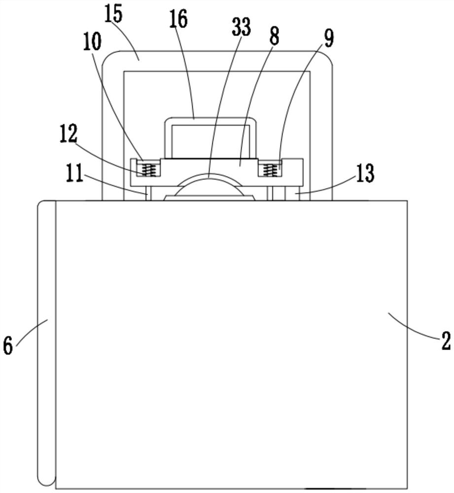
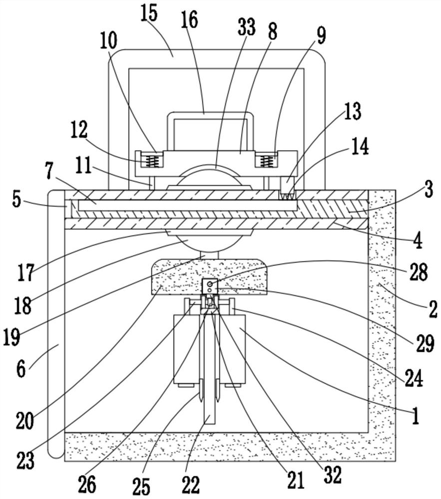
[0041] refer to Figure 1-5 , a portable foundation pit and side slope slope control device, including a protective box 2 with openings on the top and the left side, two laser meters 1 are arranged in the protective box 2, and a movable contact with the inner wall on the right side of the protective box 2 is provided. The top plate 4, the left side of the top plate 4 is fixedly connected with a baffle 6, the right side of the baffle 6 is in active contact with the left side of the protective box 2, the right side of the top plate 4 is provided with two rectangular holes 5, and the top inner wall of the rectangular hole 5 There is a penetration hole on the top, and a guide rod 3 is slidably sleeved in the rectangular hole 5. The right ends of the two guide rods 3 are fixedly connected with the inner wall of the right side of the protective box 2. The left and right guide supports, the top of the guide rod 3 is provided with an embedded groove, and a hard anti-skid rubber 7 is g...
Embodiment 2
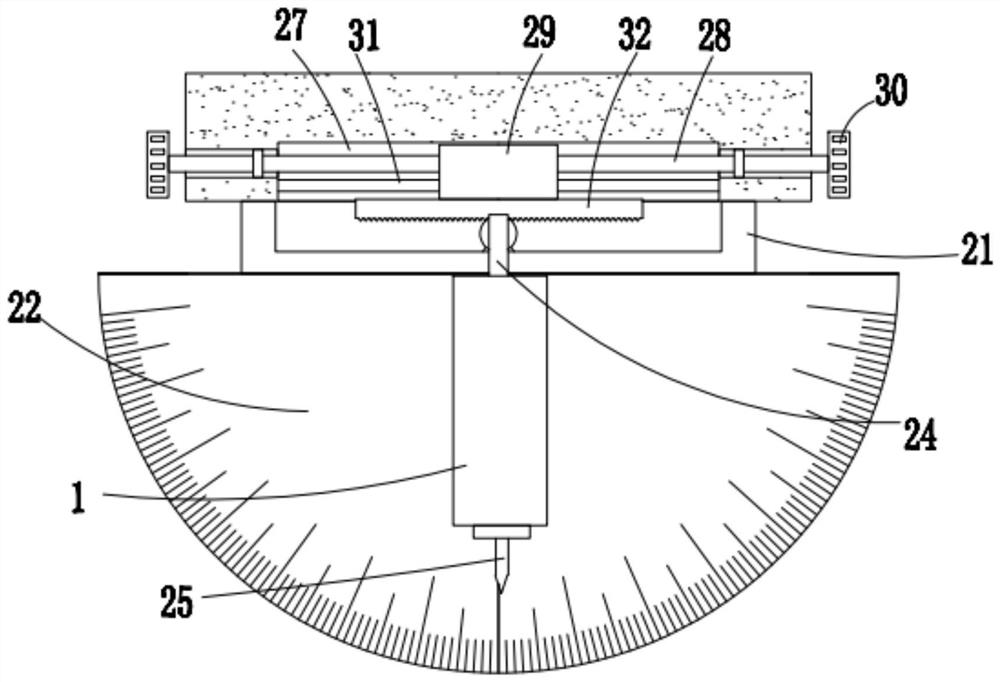
[0053] refer to Figure 6-8 On the basis of the first embodiment, this embodiment is different from the first embodiment in that: the protective box 2 is also provided with a height adjustment mechanism, and the height adjustment mechanism includes a bottom plate 44 that is in active contact with the bottom of the protective box 2, and The top right side of the bottom plate 44 is fixedly connected with a rectangular inner tube 34 whose top end is a blocking mechanism. The top end of the rectangular inner tube 34 extends into the protective box 2 , and a rectangular outer tube 35 is slidably sleeved on the rectangular inner tube 34. The rectangular outer tube The top end of 35 is fixedly connected with a rectangular box 36 with an opening on the right side, the right side of the rectangular box 36 is fixedly connected with the inner wall of the right side of the protective box 2, a rectangular seat 37 is slidably sleeved in the rectangular inner tube 34, and the rectangular seat...
PUM
 Abstract
Description
Claims
Application Information
 - R&D Engineer
- R&D Manager
- IP Professional
- Industry Leading Data Capabilities
- Powerful AI technology
- Patent DNA Extraction
Browse by: Latest US Patents, China's latest patents, Technical Efficacy Thesaurus, Application Domain, Technology Topic, Popular Technical Reports.
© 2024 PatSnap. All rights reserved.Legal|Privacy policy|Modern Slavery Act Transparency Statement|Sitemap|About US| Contact US: help@patsnap.com