
Knitting element guide bar assembly of warp knitting machine

A braiding element and bar technology, applied in the field of braiding element bar assemblies, can solve problems such as time consumption, damage, and threaded fasteners falling, and achieve the effect of simple replacement

Pending Publication Date: 2021-11-26
KARL MAYER STOLL R&D GMBH
View PDF6 Cites 0 Cited by
  • Summary
  • Abstract
  • Description
  • Claims
  • Application Information

AI Technical Summary

Problems solved by technology

The risk of threaded fasteners falling into the warp knitting machine and causing major injuries during operation is too great
Accordingly, replacement of knitting element units is time consuming and requires trained and skilled personnel

Method used


Image

  • Knitting element guide bar assembly of warp knitting machine
  • Knitting element guide bar assembly of warp knitting machine
  • Knitting element guide bar assembly of warp knitting machine

Examples


Embodiment Construction

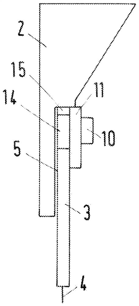
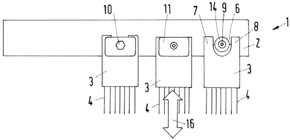
[0026] figure 1 A knitting element bar assembly 1 of a warp knitting machine is schematically shown. The bar assembly 1 has a bar 2 and a plurality of knitting element units 3 . Each knitting element unit 3 has a plurality of knitting elements 4 , which in the present case can be designed as laying needles. The knitting element unit 3 has a bar contact surface 5 with which the knitting element unit rests against the bar 3 . As will be described further below, each knitting element unit 3 is fastened detachably on the bar 2 .

[0027] exist figure 1 Three knitting element units 3 are shown in . The right knitting element unit 3 is only in contact with the bar 2 and is not already fixed there.

[0028] It can be seen that knit element unit 3 has a recess 6 which is open towards the edge of knit element unit 3 , that is to say on the side of knit element unit 3 facing away from knit element 4 .

[0029] The recess 6 is bounded laterally by two feet 7 , 8 , so that it has es...


PUM


Abstract

The invention relates to a knitting element guide bar assembly (1) of a warp knitting machine, and the knitting element guide bar assembly (1) has a guide bar (2) and a plurality of knitting element units (3), wherein each knitting element unit has a plurality of knitting elements (4); the knitting element unit (3) is attached to the guide bar (2) with a guide bar contact surface and is detachably fastened to the guide bar (2). The invention aims to simply design the service and servicing of the knitting element guide bar assembly. For this purpose, at least one knitting element unit (3) has a recess (6) open to one side, in which a clamping element (10) connected to the guide bar (2) is arranged, which clamping element acts on the knitting element unit (3) from the side opposite the contact surface of the guide bar.

Description

technical field [0001] The present invention relates to a knitting element bar assembly of a warp knitting machine, the knitting element bar assembly has a bar and a plurality of knitting element units, wherein each knitting element unit has a plurality of knitting elements, wherein the knitting element unit is in the form of a comb The bar abutment surface is attached to the comb place and can be fixed on the comb place in a detachable manner. Background technique [0002] There are basically two possibilities for fixing the knitting elements on the bars of the warp knitting machine. One possibility consists in providing knitting element receptacles on the bar, for example in the form of grooves or slits, which are oriented perpendicularly to the longitudinal extension of the bar. The braided elements are inserted individually into the grooves or slits and are then secured with covers or the like and prevented from falling out. [0003] Another possibility consists in int...

Claims


Application Information

Patent Timeline
Patent Type & Authority Applications(China)
IPC IPC(8): D04B27/24
CPCD04B27/24D04B27/06D04B37/06
Inventor K·布兰德尔
Owner KARL MAYER STOLL R&D GMBH
Learn More