New energy automobile tire damping device
A technology of new energy vehicles and shock absorbing devices, which is applied in the direction of springs/shock absorbers, vehicle springs, vehicle components, etc., which can solve the problems of wheel track changes, low motion stability, tire wear, etc., and achieve increased cushioning strength , Guarantee the grip and enhance the effect of adhesion
- Summary
- Abstract
- Description
- Claims
- Application Information
AI Technical Summary
Problems solved by technology
Method used
Image

Examples
Embodiment 1
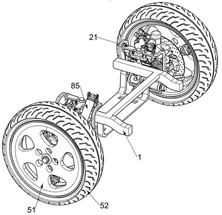
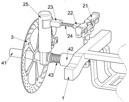
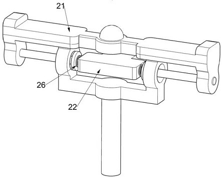
[0040] A shock absorbing device for a new energy automobile tire, such as figure 1 , figure 2 , image 3 , Figure 4 , Figure 5 , Figure 6 , Figure 7 , Figure 8 , Figure 9 , Figure 12 , Figure 14 As shown, it includes a suspension body 1, a rotating support frame 21, a T-shaped turret 22, a connecting block with a rod 23, a first return spring 24, a special-shaped support frame 25, a torsion spring 26, a transmission shaft 41, and a universal joint 42. , the second return spring 43, the tire shock absorbing assembly 5 and the suspension shock absorbing assembly 6, the suspension body 1 is symmetrically rotatably connected with a rotating support frame 21, and the rotating support frame 21 is rotatably connected with a T-shaped turret 22, A pair of torsion springs 26 are connected between the T-shaped turret 22 and the rotating support frame 21, and the T-shaped turret 22 is slidably connected with a band connecting block 23, and it is useful to connect between...
Embodiment 2
[0046] On the basis of Example 1, such as Figure 6 , Figure 8 As shown, it also includes a magnetic buffer assembly 7, the tire shock absorber assembly 5 and the suspension shock absorber assembly 6 are provided with a magnetic buffer assembly 7, the magnetic buffer assembly 7 is used for auxiliary buffering by using magnetic mutual repulsion, and the magnetic buffer assembly 7 Including magnet block 1 71 and magnet block 2 72, small damping sliding sleeve 1 54 is fixedly connected with magnet block 1 71, small damping sliding sleeve 2 55 is also provided with magnet block 1 71, and two magnet block 1 71 are mutually repellent , the large damping sliding sleeve one 62 is welded with two magnet blocks 72, and the large damping sliding sleeve two 64 is also provided with two magnet blocks 72, and the two magnet blocks two 72 repel each other.
[0047] When the rubber tire 52 and the wheel hub 51 were jumping, two magnet pieces one 71 would repel each other, and the magnet pie...
Embodiment 3
[0049] On the basis of Example 2, such as Figure 9 , Figure 10 , Figure 11 As shown, a hydraulic shock absorber assembly 8 is also included, and the top surface of the rotating support frame 21 is provided with a hydraulic shock absorber assembly 8. The hydraulic shock absorber assembly 8 is used to buffer the fixed installation block 61 and its upper body by hydraulic pressure. The hydraulic shock absorber assembly 8 includes a slotted support frame 81, a fixed base 82, a sliding piston bar 83, a rotating mounting frame 84, a sealed hydraulic pipe 85, a circular piston plate 86, a first homing spring 87, a driving motor 88, and a limit disc 89 , extension rod 810 and slotted disc 811, the top surface of rotating support frame 21 is fixedly equipped with slotted support frame 81, the top surface of two fixed mounting blocks 61 positioned at the front side is fixedly installed with fixed base 82, and the sliding piston bar 83 Hinged on the fixed base 82, the slotted suppor...
PUM
 Abstract
Description
Claims
Application Information
 - R&D
- Intellectual Property
- Life Sciences
- Materials
- Tech Scout
- Unparalleled Data Quality
- Higher Quality Content
- 60% Fewer Hallucinations
Browse by: Latest US Patents, China's latest patents, Technical Efficacy Thesaurus, Application Domain, Technology Topic, Popular Technical Reports.
© 2025 PatSnap. All rights reserved.Legal|Privacy policy|Modern Slavery Act Transparency Statement|Sitemap|About US| Contact US: help@patsnap.com