
Fin ray-free amphibious propelling device with bionic undulating fins

An amphibious and propulsion device technology, which is applied to amphibious vehicles, non-rotating propulsion elements, motor vehicles, etc., can solve the problems of low speed of wave fin movement, inability to amphibious movement, and high noise of wheel and propeller drive, and achieves reduction of fluid flow. The effect of resistance, reducing drive load, increasing compliance

Pending Publication Date: 2021-11-26
XI AN JIAOTONG UNIV
View PDF0 Cites 7 Cited by
  • Summary
  • Abstract
  • Description
  • Claims
  • Application Information

AI Technical Summary

Problems solved by technology

[0005] The technical problem to be solved by the present invention is to provide a bionic fluctuating finless finless amphibious propulsion device for the above-mentioned deficiencies in the prior art, so as to solve the problems of complex transmission mechanism, complex switching between amphibious and land modes, and wheel and paddle drive noise in existing amphibious robots. Large, low flexibility and large environmental disturbances, as well as the low speed of the undulating fin driven by the conventional steering gear, the low bearing capacity of the traditional cam, crankshaft and connecting rod mechanism, and the inability to amphibious movement, etc.

Method used


Image

  • Fin ray-free amphibious propelling device with bionic undulating fins
  • Fin ray-free amphibious propelling device with bionic undulating fins
  • Fin ray-free amphibious propelling device with bionic undulating fins

Examples


Embodiment Construction

[0037] The technical solutions in the embodiments of the present invention will be clearly and completely described below in conjunction with the accompanying drawings in the embodiments of the present invention. Obviously, the described embodiments are part of the embodiments of the present invention, not all of them. Based on the embodiments of the present invention, all other embodiments obtained by persons of ordinary skill in the art without making creative efforts belong to the protection scope of the present invention.

[0038] In describing the present invention, it should be understood that the terms "center", "longitudinal", "transverse", "upper", "lower", "front", "rear", "left", "right", " The orientation or positional relationship indicated by "vertical", "horizontal", "top", "bottom", "inner", "outer", "side", "end", "side", etc. is based on the Orientation or positional relationship is only for the convenience of describing the present invention and simplifying ...


PUM


Abstract

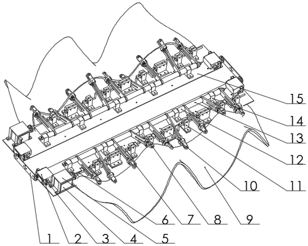
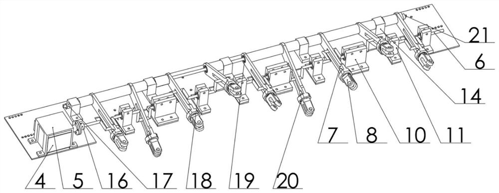
The invention discloses a fin ray-free amphibious propelling device with bionic undulating fins, which is characterized in that two end fixed type crankshaft swing rod transmission modules are arranged on corresponding bottom plates correspondingly, and the front ends and the rear ends of the two bottom plates are connected with a front waterproof steering engine amphibious mode switching module and a rear waterproof steering engine amphibious mode switching module correspondingly; the front and back waterproof steering engine land and water mode switching module is used for maintaining the state of the bottom plate; each end fixed type crankshaft swing rod transmission module is connected with one flexible fin-ray-free flexible fin through the corresponding drive swing rod mechanism, and the joint of each drive swing rod mechanism and the corresponding flexible fin-ray-free flexible fin is provided with a rotational degree of freedom to drive the fin surface of the corresponding flexible fin-ray-free flexible fin to achieve fluctuating motion. The problems that an existing amphibious robot is complex in transmission mechanism, complex in amphibious mode switching, large in wheel paddle driving noise, low in flexibility and large in environment disturbance, the movement speed of fluctuation fins driven by a conventional steering engine is low, and a traditional cam and crankshaft connecting rod mechanism is low in bearing capacity and cannot conduct amphibious movement are solved.

Description

technical field [0001] The invention belongs to the technical field of amphibious robots, in particular to a bionic fluctuating finless finless amphibious propulsion device. Background technique [0002] China has millions of square kilometers of sea area and tens of thousands of kilometers of continental coastline. With the development of my country's national ocean development strategy, it is necessary to study amphibious propulsion devices that can meet the needs of efficient underwater propulsion and high maneuverability on land. Amphibious robots replace humans in military intelligence collection and offshore area alert tasks, which is of great strategic significance for improving the technological level of unmanned weapons in our country. In addition, amphibious robots are also widely used in civil fields such as mineral resource exploration and development and marine life protection. prospect. [0003] Current traditional amphibious robots, such as amphibious boats and...

Claims


Application Information

Patent Timeline
IPC IPC(8): B60F3/00B63H1/37B62D57/02
CPCB60F3/0007B60F3/003B63H1/37B62D57/02
Inventor 胡桥曾杨彬童保成李士杰张堂佳
Owner XI AN JIAOTONG UNIV
Learn More