
Ejection type injection molding machine convenient to maintain the heating cylinder

A heating cylinder and injection molding machine technology, applied in the field of injection molding machines, can solve the problems of heating cylinder damage, heating cylinder falling, smashing and dismantling personnel, etc., to achieve the effect of reducing manual triggering, avoiding falling, and convenient viewing

Inactive Publication Date: 2021-11-26
蒋成建
View PDF2 Cites 0 Cited by
  • Summary
  • Abstract
  • Description
  • Claims
  • Application Information

AI Technical Summary

Problems solved by technology

[0006] The purpose of the present invention is to provide a convenient ejection injection molding machine for heating cylinder maintenance, to solve the existing injection molding machines on the market proposed by the above background technology, when the heating cylinder needs to be repaired, it needs to be repaired and heated The bolts on both sides of the heating cylinder must be completely removed, and then the heating cylinder can be removed from the installation platform. The disassembly is cumbersome, and the mass of the heating cylinder is relatively large. When removing the bolts on both sides of the heating cylinder, it is easy to cause the heating cylinder to fall. There is a problem that the heating cylinder is damaged or smashed into the dismantling personnel.

Method used


Image

  • Ejection type injection molding machine convenient to maintain the heating cylinder
  • Ejection type injection molding machine convenient to maintain the heating cylinder
  • Ejection type injection molding machine convenient to maintain the heating cylinder

Examples


Embodiment Construction

[0028] Based on the embodiments of the present invention, all other embodiments obtained by persons of ordinary skill in the art without making creative efforts belong to the protection scope of the present invention.

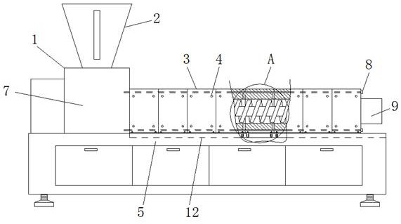
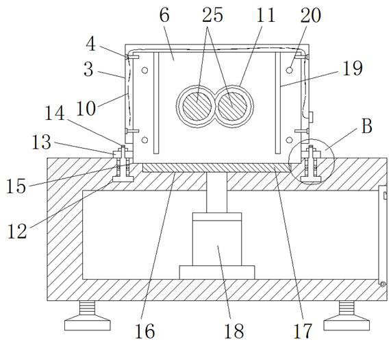
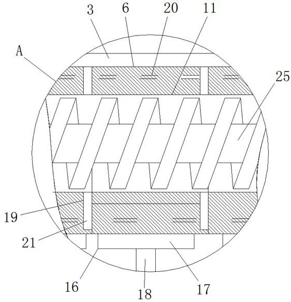
[0029] see Figure 1-7 , the present invention provides a technical solution: a ejection injection molding machine for convenient maintenance of the heating cylinder, comprising an injection molding machine 1, a feeding hopper 2, a heating cover 3, a fixing bolt 4, a mounting table 5, a heating cylinder 6, a feeding Material box 7, fastening bolt 8, injection port 9, heating wire 10, heating chamber 11, limit chute 12, mounting plate 13, connecting column 14, mounting groove 15, receiving groove 16, ejector plate 17, pushing device 18. Splicing interface 19, piercing hole 20, splicing strip 21, bearing 22, fastening nut 23, limit table 24 and screw propulsion rod 25, a feeding hopper 2 is arranged above the injection molding machine 1, and the feeding hopper 2 ...


PUM


Abstract

The invention discloses an ejection type injection molding machine convenient to maintain a heating cylinder. The ejection type injection molding machine comprises an injection molding machine body, a feed hopper, a heating mantle, a fixing bolt, a mounting table, a feeding box, an injection molding port, a heating wire, a heating cavity and a bearing, wherein the feed hopper is arranged above the injection molding machine body; the lower portion of the feed hopper is connected with the feeding box; the mounting table is arranged at one side of the feeding box; meanwhile, the output end of the feeding box is connected with a spiral pushing ram; a mounting groove is formed in the middle of the upper portion of the mounting table; the heating cylinder is placed on the mounting groove; limiting chutes are formed in the upper end faces, at the two sides of the mounting groove, of the mounting table; connecting columns are arranged in the limiting chutes in a penetrating mode; a splicing opening is formed in one end of the heating cylinder; and a splicing strip is integrally formed at the other end of the heating cylinder. According to the ejection type injection molding machine convenient to maintain the heating cylinder, by improving the structure of the heating cylinder of an existing injection molding machine, the heating cylinder can be conveniently detached, and the heating cylinder can be prevented from falling off, and accidents can be avoided.

Description

technical field [0001] The invention relates to the technical field of injection molding machines, in particular to an ejection type injection molding machine which facilitates the maintenance of a heating cylinder. Background technique [0002] Most of the injection molding machines use screw-type plasticization to transfer the heated and melted plastic through the heat supply of an external heater and the screw-type rotation, and then move out after being molded by a heating cylinder with a specific molding cavity. For example, the reference document application number: CN201810930183.5, authorization announcement number: CN109177029B A kind of plastic shoe injection molding machine with strong stability, including feed inlet, electromagnet, slide rod, magnet, screening basket and screening hole, the inner wall of the feed inlet is equipped with electromagnetic Iron, the top of the electromagnet is equipped with a slide bar, the outside of the slide bar is sleeved with a m...

Claims


Application Information

Patent Timeline
Patent Type & Authority Applications(China)
IPC IPC(8): B29C45/17B29C45/58B29C45/62
CPCB29C45/176B29C45/1761B29C45/1775B29C45/62B29C45/58
Inventor 蒋成建
Owner 蒋成建
Learn More