Zero-voltage turn-off zero-current turn-on high-gain Cuk converter

A zero-voltage turn-off and zero-current technology, applied in the field of DC-DC converters, can solve the problems of increased switching loss, switching loss, waveform overshoot, etc., and achieve the goal of eliminating turn-on loss, eliminating turn-off loss, and reducing switching loss Effect

Pending Publication Date: 2021-11-23
CHINA THREE GORGES UNIV
View PDF0 Cites 0 Cited by
  • Summary
  • Abstract
  • Description
  • Claims
  • Application Information

AI Technical Summary

Problems solved by technology

[0003] (1) Switching loss problem: During the switching process of the power switch tube, the voltage and current of the power switch tube are not zero, and there is an overlapping area, which is the switching loss of the power switch tube
There is a linear relationship between switching loss and switching frequency. After the switching frequency increases, the switching loss will increase significantly.
[0004] (2) EMI (Electromagnetic Interference) electromagnetic interference effect: When the converter works at high frequency, the voltage and current change quickly, the waveform will have obvious overshoot, and the switch tube will have to generate higher du / dt and di / dt, it will affect the power supply itself and the surrounding electronic equipment, and there will be switching noise. After the switching frequency is further increased, the EMI problem will become more serious

Method used


Image

  • Zero-voltage turn-off zero-current turn-on high-gain Cuk converter
  • Zero-voltage turn-off zero-current turn-on high-gain Cuk converter
  • Zero-voltage turn-off zero-current turn-on high-gain Cuk converter

Examples


Embodiment

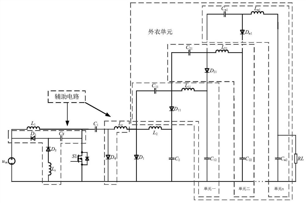
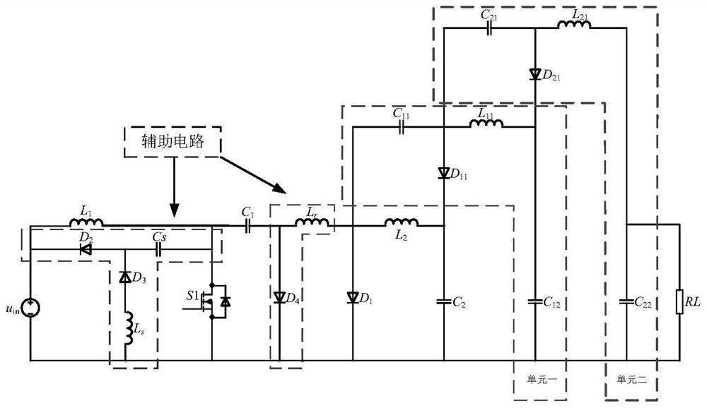
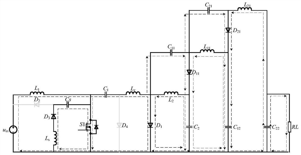
[0087] Such as figure 2 As shown, taking two coat units as an example:

[0088] A zero-voltage turn-off zero-current turn-on high-gain Cuk converter includes a traditional Cuk converter, two coat units and an auxiliary circuit. Wherein, the traditional Cuk converter includes two inductors L1, L1, a power switch S1, a diode D1 and two capacitors C1, C2. The first garment unit contains an inductor L11, two capacitors C11, C12 and a diode D11. The second garment unit comprises an inductor L21, two capacitors C21, C22 and a diode D21. The auxiliary circuit part includes a zero-current inductor Lr, an auxiliary inductor Ls, a zero-voltage capacitor Cs, and three diodes D2, D3, and D4. Its circuit connection relationship is:

[0089] In a traditional Boost converter, one end of the inductor L1 is connected to the positive pole of the input power supply, the other end of the inductor L1 is connected to the drain of the power switch tube S1, and one end of the capacitor C1, the s...


PUM


Abstract

The invention discloses a zero-voltage turn-off and zero-current turn-on high-gain Cuk converter. The converter comprises a main circuit and an auxiliary circuit. The main circuit comprises a Cuk converter and at least one coat unit. The Cuk converter comprises two inductors L1 and L2, a power switch tube S1, a diode D1 and two capacitors C1 and C2. The auxiliary circuit comprises a zero-current inductor Lr, an auxiliary inductor Ls, a zero-voltage capacitor Cs, a diode D2, a diode D3 and a diode D4. According to the converter, zero-voltage turn-off and zero-current turn-on of the power switch tube are achieved, switching loss on the power switch tube S1 is eliminated, the purpose of soft switching lossless is achieved, and the efficiency of the converter can be improved.

Description

technical field [0001] The invention relates to a DC-DC converter, in particular to a zero-voltage turn-off zero-current turn-on high-gain Cuk converter. Background technique [0002] In the existing switching power supply technology, the Cuk coat circuit achieves high voltage gain very well, but in the high-gain DC / DC converter, in order to reduce the cost of the converter and increase the power density of the converter, it is necessary to improve the converter However, it is still difficult to realize the high-frequency operation of the converter. The main reason is that as the operating frequency of the converter increases, the switching loss of the switching tube will increase accordingly, which will lead to a decrease in the working efficiency of the converter and an increase in heat generation. In addition, the radiator volume and weight also increase. The increase in switching frequency mainly produces the following two problems: [0003] (1) Switching loss problem...

Claims


Application Information

Patent Timeline
Patent Type & Authority Applications(China)
IPC IPC(8): H02M3/07H02M1/08H02M1/44
CPCH02M3/07H02M3/005H02M1/083H02M1/44Y02B70/10
Inventor 邾玢鑫蓝海赵宇辉支树播杨楠李振华王凯宏
Owner CHINA THREE GORGES UNIV
Why Eureka
Try Eureka