
Three-phase power factor correction device

A correction device, three-phase power technology, applied in the output power conversion device, the conversion of AC power input to DC power output, high-efficiency power electronic conversion, etc. The probability of danger, the convenience of designing circuits, and the effect of suppressing electromagnetic interference

Active Publication Date: 2021-11-23
SUZHOU MEAN WELL TECH CO LTD +1
View PDF4 Cites 0 Cited by
  • Summary
  • Abstract
  • Description
  • Claims
  • Application Information

AI Technical Summary

Problems solved by technology

However, the six-switch three-phase power factor correction circuit uses too many switches, the control is complicated, and the cost is high. When common mode noise occurs, the two power switches 10 connected in series on each bridge arm have the risk of a direct short circuit. The reliability requirements of power drive control are very high

Method used


Image

  • Three-phase power factor correction device
  • Three-phase power factor correction device
  • Three-phase power factor correction device

Examples


Embodiment Construction

[0031] The embodiments of the present invention will be further explained in conjunction with related figures below. Wherever possible, the same reference numbers are used throughout the drawings and description to refer to the same or like components. In the drawings, shapes and thicknesses may be exaggerated for simplification and convenient notation. It should be understood that elements not particularly shown in the drawings or described in the specification are forms known to those skilled in the art. Those skilled in the art can make various changes and modifications based on the content of the present invention.

[0032] Unless otherwise specified, some conditional sentences or words, such as "may", "may", "maybe", or "may", are usually intended to express that the embodiment of the present case has, but can also be interpreted as features and elements that may not be required , or step. In other embodiments, these features, elements, or steps may not be required.

...


PUM


Abstract

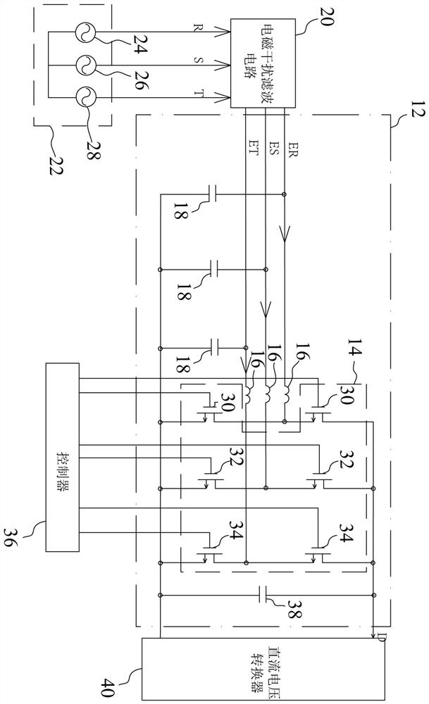
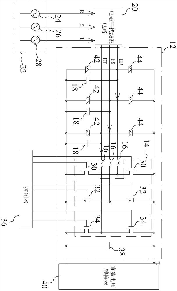
The invention discloses a three-phase power factor correction device. The three-phase power factor correction device comprises a three-phase change-over switch group, three inductors and three filter capacitors, wherein the three-phase change-over switch group is coupled between a first output end and a second output end; all the inductors are coupled with the three-phase change-over switch group; the three-phase change-over switch group receives the three-phase electromagnetic interference filtering voltage through the inductor and converts the three-phase electromagnetic interference filtering voltage into a direct-current voltage; and all the filter capacitors are respectively coupled with all the inductors and are coupled with the second output end, each filter capacitor is connected between the corresponding inductor and the second output end, and all the filter capacitors filter common-mode noise of three-phase electromagnetic interference filtering voltage so as to reduce the probability of danger.

Description

technical field [0001] The invention relates to a correction device, and in particular to a three-phase power factor correction device. Background technique [0002] Power factor refers to the relationship between effective power and total power consumption, that is, the ratio of effective power divided by total power consumption. Generally speaking, power factor can be used to measure the degree of power utilization. When the power factor value The larger the value, the higher the power utilization rate. Power factor correctors applied to power supplies are mostly used to control and adjust the time and waveform of AC current input to make it as consistent as possible with the DC voltage waveform, so that the power factor value is close to 1, and avoid power equipment system consumption. Electricity exceeds its specification, creating unnecessary disturbances. [0003] From the above, it can be seen that low power factor means low power efficiency, and the lower the power...

Claims


Application Information

Patent Timeline
Patent Type & Authority Applications(China)
IPC IPC(8): H02M1/42H02M1/44H02M1/12H02M1/38H02M7/219
CPCH02M1/4233H02M1/44H02M1/126H02M1/38H02M7/219H02M7/2173Y02B70/10
Inventor 钟郁纬刘亚哲黄士荣王士昕
Owner SUZHOU MEAN WELL TECH CO LTD
Learn More