
Wireless transmission thermoelectric device

A thermoelectric device and wireless transmission technology, which can be used in thermoelectric devices, electrical components, thermoelectric devices that only use the Peltier or Seebeck effect, etc.

Pending Publication Date: 2021-11-23
ZHEJIANG SCI-TECH UNIV
View PDF1 Cites 0 Cited by
  • Summary
  • Abstract
  • Description
  • Claims
  • Application Information

AI Technical Summary

Problems solved by technology

However, it only involves wireless transmission coils for transmission, and does not disclose its specific winding structure, and still adopts the traditional method of setting the wireless transmission coil outside the thermoelectric device, such as one end, which will make the thickness of the thermoelectric device thicker, which is not conducive to Miniaturization limits its application

Method used


Image

  • Wireless transmission thermoelectric device
  • Wireless transmission thermoelectric device
  • Wireless transmission thermoelectric device

Examples


Embodiment Construction

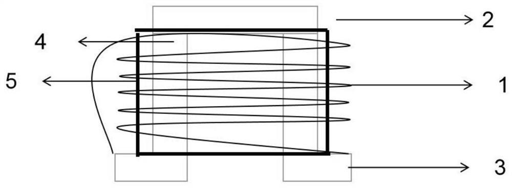
[0027] Such as Figure 1-2 As shown, the present invention provides a wireless transmission thermoelectric device, a wireless transmission thermoelectric device, including sequentially connected thermoelectric device groups, conversion circuits, wireless transmission, power storage and control circuits, and using power storage and control circuits to supply power to loads The thermoelectric device includes a semiconductor column 4 and an electrode 3, wherein the wireless transmission coil includes: a transmitting coil and a receiving coil, wherein the two ends of the transmitting coil are connected to the electrode 3 of the thermoelectric device, and the wireless transmission The transmitter coil 1 of the coil is wound on the device semiconductor pillar 4 of the thermoelectric group. By winding the emitting coil on the semiconductor pillars of the thermoelectric device group, and the upper end does not exceed the top of the semiconductor pillars, the space in the thickness dir...


PUM


Abstract

The invention relates to a wireless transmission thermoelectric device, which comprises a thermoelectric device, a conversion circuit, a wireless transmission coil and a power supply storage and control circuit, wherein a transmitting coil or a receiving coil of the wireless transmission coil is wound on a device semiconductor column of the thermoelectric set. By winding the transmitting coil or the receiving coil on the device semiconductor column of the thermoelectric group, the thermoelectric device can be thinned, and the coil is wound densely, so that the sensing efficiency of the coil is improved.

Description

technical field [0001] The invention relates to a wireless transmission thermoelectric device. Background technique [0002] At present, the diversified utilization of energy has become an important technical approach to solve energy and environmental problems. As a green energy technology and environmentally friendly refrigeration technology, thermoelectric conversion technology has received extensive attention. Thermoelectric devices are based on the temperature difference of PN semiconductors and directly convert thermal energy into electrical energy, which is an effective recycling method with many advantages. However, there are few studies on existing thermoelectric structures, which mainly focus on the modification of materials, and the electric energy converted from the thermal energy of existing thermoelectric devices needs to be transmitted through wires. At present, conventional wires are generally used to directly transmit electric energy to energy The storage d...

Claims


Application Information

Patent Timeline
Patent Type & Authority Applications(China)
IPC IPC(8): H02J50/10H01L35/32H10N10/17
CPCH02J50/10H10N19/101
Inventor 杨嘉泉吴小平宋昌盛王顺利王朋高海琪崔灿
Owner ZHEJIANG SCI-TECH UNIV
Learn More