
Horizontally-polarized omnidirectional metasurface antenna

A horizontal polarization, metasurface technology, applied in the application field of wireless signal transmission technology, can solve the problems of large size, complex feeding structure, difficult broadband, etc., and achieve the effect of stabilizing broadband radiation characteristics

Active Publication Date: 2021-11-23
UNIV OF ELECTRONICS SCI & TECH OF CHINA
View PDF6 Cites 3 Cited by
  • Summary
  • Abstract
  • Description
  • Claims
  • Application Information

AI Technical Summary

Problems solved by technology

[0003] In recent years, the research on horizontally polarized omnidirectional antennas is mainly divided into the following categories: Alford loop antennas and their deformations, slot antennas, combined loop antennas, rotating field antennas, etc.; Alford is a typical horizontally polarized omnidirectional antenna, with Small size, but its working bandwidth is very narrow; slot antennas include slotted cylindrical slots and waveguide slot antennas, this type of horizontal omnidirectional antenna is easy to achieve low sidelobe and high aperture surface utilization characteristics, but its size is relatively large, Therefore, it is difficult to achieve broadband; the combined loop antenna simulates a uniform current loop by connecting multiple radiation elements in parallel on the coaxial line to achieve horizontally polarized omnidirectional radiation. Although this type of antenna can achieve a relatively wide bandwidth, its structure is generally relatively Complex; the rotating field antenna is composed of a pair of cross-arranged dipoles. Their currents are of equal amplitude and phase quadrature, and realize omnidirectional radiation on the horizontal plane. This type of antenna is widely used because of its very wide bandwidth. In the transmission of radio broadcasting signals, but the rotating field antenna has strict requirements on the quadrature phase of the two ports, so its feeding structure is relatively complicated

Method used


Image

  • Horizontally-polarized omnidirectional metasurface antenna
  • Horizontally-polarized omnidirectional metasurface antenna
  • Horizontally-polarized omnidirectional metasurface antenna

Examples


Embodiment 1

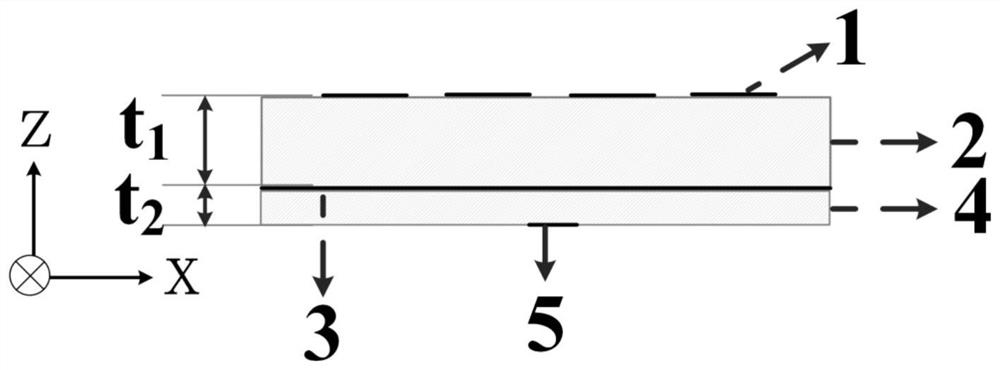
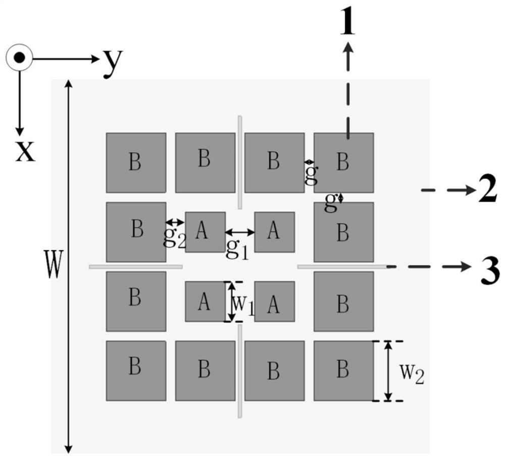
[0026] This embodiment provides a horizontally polarized omnidirectional metasurface antenna, the structure of which is as follows figure 1 As shown, it includes: a metasurface radiation structure 1, an upper dielectric substrate 2, a metal ground plate 3, a lower dielectric substrate 4 and a microstrip feed structure 5, the metasurface radiation structure 1 is arranged on the upper surface of the upper dielectric substrate 2, The metal ground plate 3 is disposed on the lower surface of the upper dielectric substrate 2 , the lower dielectric substrate 4 is disposed on the lower surface of the metal ground plate 3 , and the microstrip feeding structure 5 is disposed on the lower surface of the lower dielectric substrate 4 .

[0027] In this embodiment, the upper dielectric substrate 2 is made of Arlon TC350 plate with a dielectric constant of 3.5 and a thickness of t 1 =4mm, the lower dielectric substrate 4 adopts Neltec NY9260 (IM) plate with a dielectric constant of 2.6, and ...


PUM


Abstract

The invention belongs to the field of wireless signal transmission technology application, and particularly provides a horizontally-polarized omnidirectional metasurface antenna to simultaneously meet the requirements of broadband, miniaturization and simple structure. The antenna comprises a micro-strip feed structure 5, a lower dielectric substrate 4, a metal grounding plate 3, an upper dielectric substrate 2 and a metasurface radiation structure 1 which are sequentially stacked from bottom to top, wherein the metasurface radiation structure 1 is composed of four square patches A and twelve square patches B, the four square patches A are arranged in the center of the upper dielectric substrate in a 2 * 2 array, and the twelve square patches B are arranged around the four square patches A. The strongest current distribution position of a horizontal omnidirectional polarization mode is always fixed on a specific patch through the structural design of the metasurface radiation structure, and a reasonable feed structure is arranged to ensure that the desired horizontal-polarization omnidirectional radiation mode is efficiently excited in a broadband range.

Description

technical field [0001] The invention belongs to the application field of wireless signal transmission technology, and relates to a horizontally polarized omnidirectional antenna structure, in particular to a horizontally polarized omnidirectional metasurface antenna. Background technique [0002] Omnidirectional antennas are widely used in wireless broadcasting, satellites, global positioning systems, wireless local area networks and mobile devices because of their uniform radiation characteristics in a 360° direction on a certain plane; such as mobile phones, cordless phones, FM radios, etc. Horizontally polarized omnidirectional antenna refers to an antenna that can radiate and receive signals uniformly on the horizontal azimuth plane 360° and is polarized in the horizontal plane. It is widely used in radar, satellite communication, mobile communication, and radio frequency communication. Its effective coverage is wider. [0003] In recent years, the research on horizonta...

Claims


Application Information

Patent Timeline
IPC IPC(8): H01Q1/38H01Q1/50H01Q1/48H01Q15/00H01Q3/44
CPCH01Q1/38H01Q1/50H01Q1/48H01Q15/0086H01Q15/002H01Q3/44
Inventor 陈涌频刘思豪胡俊孟敏郭俊雷
Owner UNIV OF ELECTRONICS SCI & TECH OF CHINA
Learn More