
A circuit and method for realizing PCIE resource automatic allocation and a storage medium

A technology for automatic allocation and resource allocation. It is applied in resource allocation, electrical digital data processing, instruments, etc. It can solve the problems of wasting server PCIE resources, unable to provide PCIE interface of CPU, and affecting the data transmission efficiency of server processors and storage devices.

Pending Publication Date: 2021-11-23
SUZHOU LANGCHAO INTELLIGENT TECH CO LTD
View PDF0 Cites 1 Cited by
  • Summary
  • Abstract
  • Description
  • Claims
  • Application Information

AI Technical Summary

Problems solved by technology

When the customer is actually using it, if some of the NVME disks are unplugged, the speed of the remaining NVME hard disks is still Gen1, and the bandwidth is still X1, and the PCIE resources of the CPU corresponding to the unplugged NVME disks are completely idle at this time state, it is impossible to re-provide the PCIE interface of the CPU to the NVME hard disk that is still in use, resulting in a waste of PCIE resources on the server
Affects the data transmission efficiency between the server processor and the storage device, and limits the performance of the processor

Method used


Image

  • A circuit and method for realizing PCIE resource automatic allocation and a storage medium
  • A circuit and method for realizing PCIE resource automatic allocation and a storage medium
  • A circuit and method for realizing PCIE resource automatic allocation and a storage medium

Examples


Embodiment 1

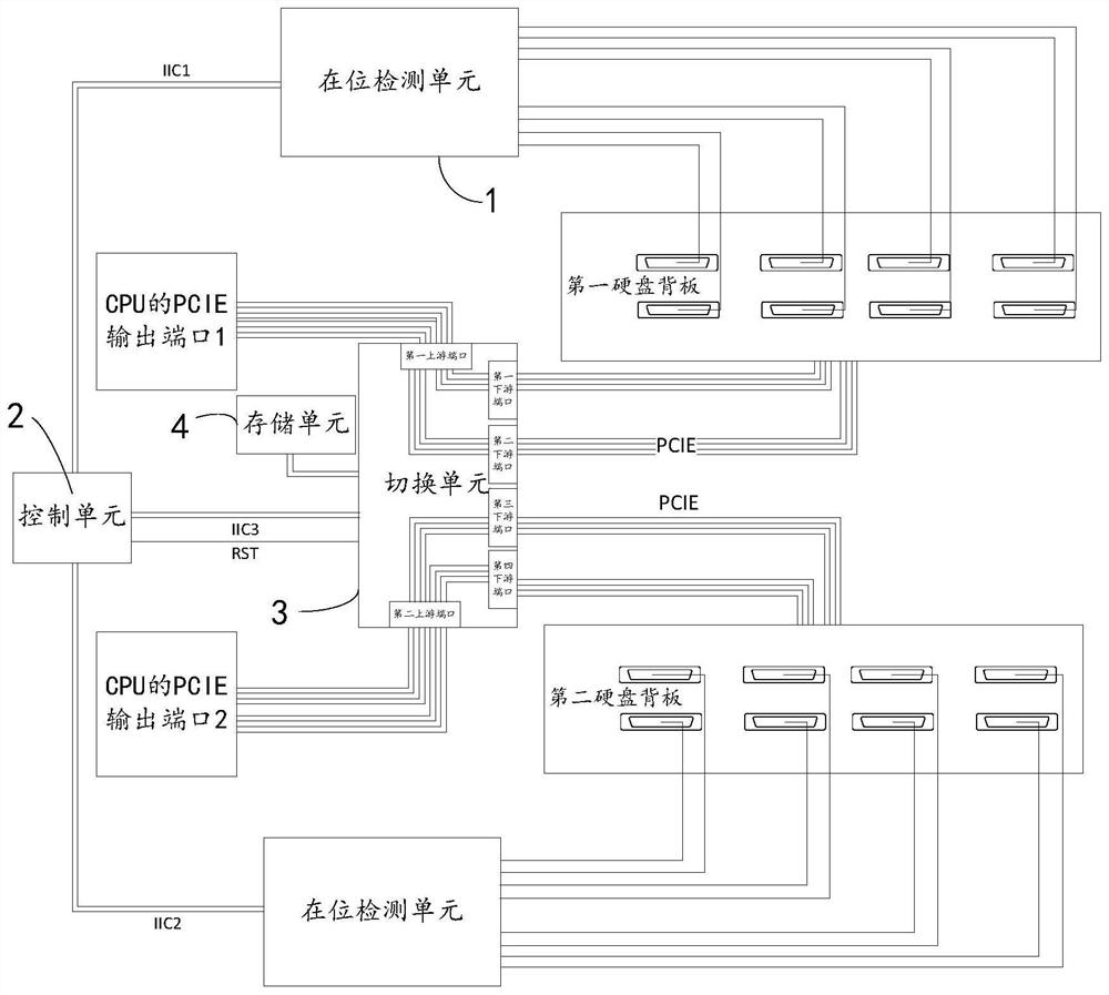
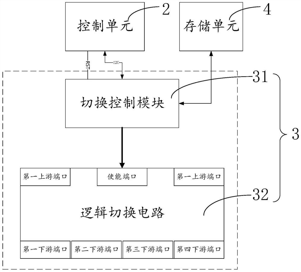
[0048] refer to figure 1 As shown, the embodiment of the present application provides a circuit for realizing automatic allocation of PCIE resources, including:

[0049] Electrically connected to several in-position acquisition units 1 of the presence indication circuits of the first hard disk backplane and the second hard disk backplane; in this embodiment, the first hard disk backplane and the second hard disk backplane respectively pass 8 hard disk interfaces are connected to 8 hard disks, and each hard disk interface is respectively provided with an in-position indicating circuit; The in-position acquisition unit 1 sends a first level signal; when the hard disk interface on the hard disk backplane is plugged with a hard disk, the in-position indicating circuit sends a second level signal to the in-position acquisition unit 2 .

[0050] Several described in-position acquisition units 1 are connected to control unit 2 by bus, in the specific implementation process, describe...

Embodiment 2

[0064] This embodiment provides a method for realizing automatic allocation of PCIE resources, see Figure 5 As shown, the method for realizing the automatic allocation of PCIE resources includes:

[0065] S100, the in-position acquisition unit acquires the in-position information of the hard disk on the hard disk backboard according to the output signal of the in-position indicating circuit;

[0066] S200, the control unit polls each of the in-position acquisition units to acquire the in-position information of the hard disk on each hard disk backboard;

[0067] S300, the control unit sends the corresponding presence information to a corresponding switching unit;

[0068] In the specific implementation process, the switching unit and the in-position acquisition unit are configured with a unique identification address, and the control unit configures a mapping table between the switching unit and the in-position acquisition unit, and the mapping table will be corresponding in...

Embodiment 3

[0084] This embodiment provides a storage medium for realizing automatic allocation of PCIE resources. The storage medium for realizing automatic allocation of PCIE resources stores at least one instruction, and executing the instruction implements the described method for realizing automatic allocation of PCIE resources.

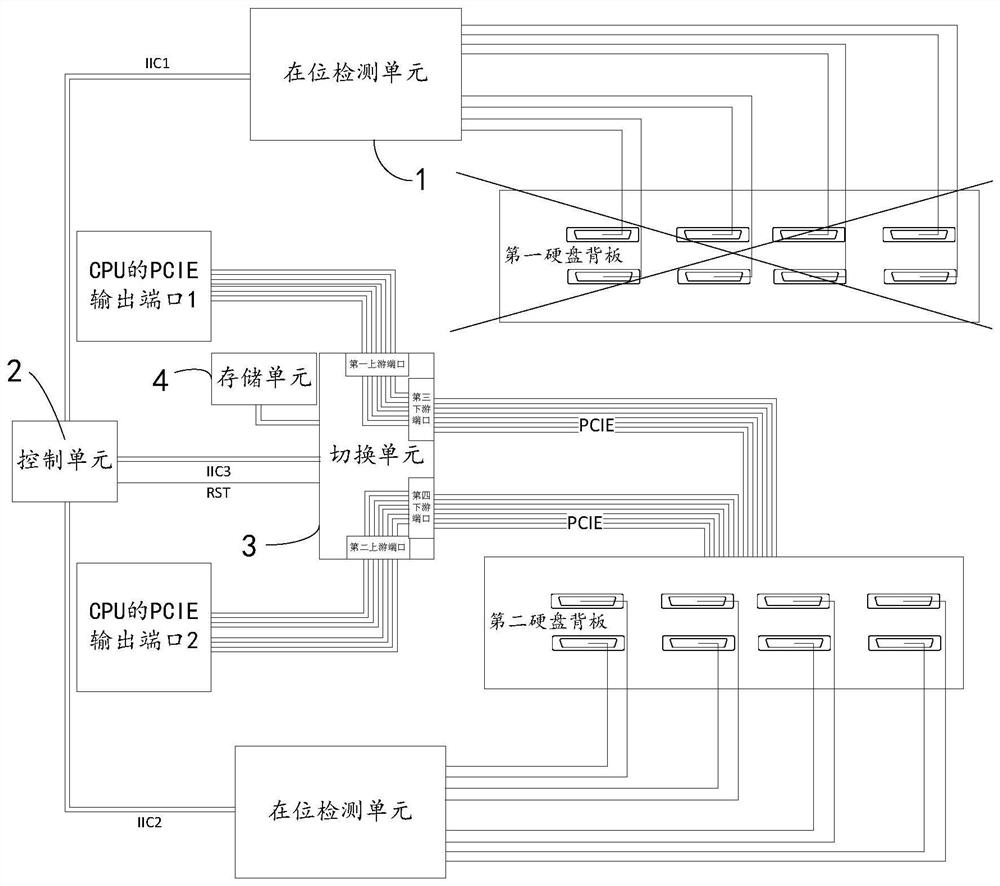
[0085] The circuit provided by the application to realize the automatic allocation of PCIE resources is connected to the PCIE output port of the server CPU through the first upstream port and the second upstream port of several switching units 3; through the first downstream port and the second downstream port of the switching unit 3 The hard disks on the first hard disk backboard are connected, and the hard disks on the second hard disk backboard are connected through the third downstream port and the fourth downstream port of the switching unit 3 . The signals of the in-position indicating circuits of the hard disks on several first hard disk backplanes an...


PUM


Abstract

The invention relates to a circuit and method for realizing PCIE resource automatic allocation and a storage medium. The circuit comprises: a plurality of in-place acquisition units connected to a plurality of hard disk backboard in-place indication circuits; the plurality of in-place acquisition units that are connected with the control unit through a bus, the control unit is connected with the plurality of switching units through a bus, the in-place acquisition units detect in-place information of a hard disk on a hard disk backboard and send the in-place information to the control unit through the bus, and the control unit sends the corresponding in-place information to the corresponding switching units; the switching unit that is electrically connected with the storage unit, the storage unit stores an allocation strategy, and the switching unit selects the allocation strategy according to the in-place information; the upstream port of the switching unit that is electrically connected with the PCIE output port of the CPU, and the downstream port of the switching unit is electrically connected with the hard disk backboard. According to the invention, the PCIE resources of the processor can be automatically allocated to the hard disk backboards in use when the hard disk backboards connected with the processor are absent, and the PCIE resources of the processor are fully utilized to ensure the performance of the processor.

Description

technical field [0001] The present application relates to the field of server hardware design, in particular to a circuit, method and storage medium for realizing automatic allocation of PCIE resources. Background technique [0002] With the improvement of server processing capacity, in order to realize computing and storage functions, a large number of NVME, SATA, and SAS hard disk storage devices are used in the server. The storage of large amounts of data requires high-speed communication between the processor of the server and the storage device; In the design of the server, a high-speed PCIE bus is often used for data transmission between the CPU and the storage device. [0003] In the prior art, the design of the PCIE bus between the server processor and the storage device is fixed. For example: the CPU is connected to multiple NVME hard disks through a PCIE bus with a bandwidth of X1. The speed of each hard disk is Gen1 and the bandwidth is X1. Since the PCIE bus bet...

Claims


Application Information

Patent Timeline
IPC IPC(8): G06F13/42G06F9/50
CPCG06F13/4282G06F9/5027G06F2213/0026G06F2213/0016Y02D10/00
Inventor 施世磊
Owner SUZHOU LANGCHAO INTELLIGENT TECH CO LTD
Learn More