
Base plate glass lifting and extracting rack arm device

A frame arm and glass technology, which is applied in the direction of grinding machine tool parts, grinding feed movement, metal processing equipment, etc., can solve problems such as damage, lack of joint devices, lack of flexible contact, etc., to avoid top pressure damage, Ensure safety and reliability, and realize the effect of flexible contact

Pending Publication Date: 2021-11-23
RAINBOW (HEFEI) LIQUID CRYSTAL GLASS CO LTD
View PDF0 Cites 3 Cited by
  • Summary
  • Abstract
  • Description
  • Claims
  • Application Information

AI Technical Summary

Problems solved by technology

[0003] The existing technology has the following problems: the grinding process in the production process occupies an important position in the entire production process flow, and the quality of grinding depends on the overall grinding equipment and production process flow, but the existing G6 generation substrate grinding equipment and process flow Realize the grinding process of the edge and corner of the glass substrate. In this process, the external mechanical arm and the lifting and extracting device are required to realize the lifting and extraction of the substrate glass. However, when the substrate glass is lifted and extracted, it lacks a flexible contact. , the lifting and extracting arm device that can be freely extended and contacted, and the lifting and extraction is stable and convenient to use cannot meet the current production needs. When the existing substrate glass external robot arm is used alone, it directly contacts the substrate glass, which is easy to cause damage. Lack of An intermediate connecting device, which cannot better meet the current lifting and extraction production needs

Method used


Image

  • Base plate glass lifting and extracting rack arm device
  • Base plate glass lifting and extracting rack arm device
  • Base plate glass lifting and extracting rack arm device

Examples


Embodiment Construction

[0025] The following will clearly and completely describe the technical solutions in the embodiments of the present invention with reference to the accompanying drawings in the embodiments of the present invention. Obviously, the described embodiments are only some, not all, embodiments of the present invention. Based on the embodiments of the present invention, all other embodiments obtained by persons of ordinary skill in the art without making creative efforts belong to the protection scope of the present invention.

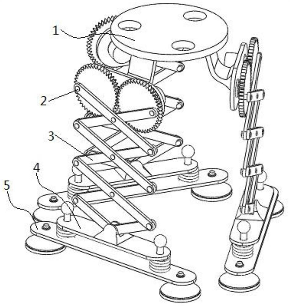
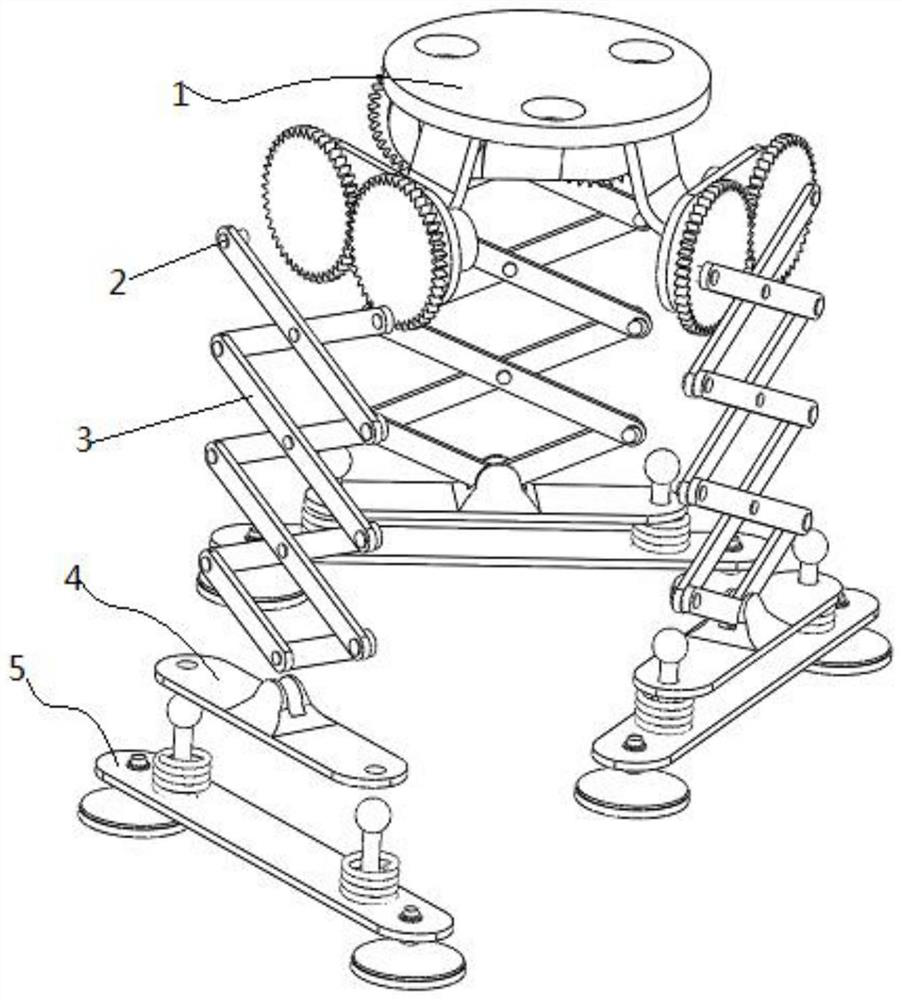
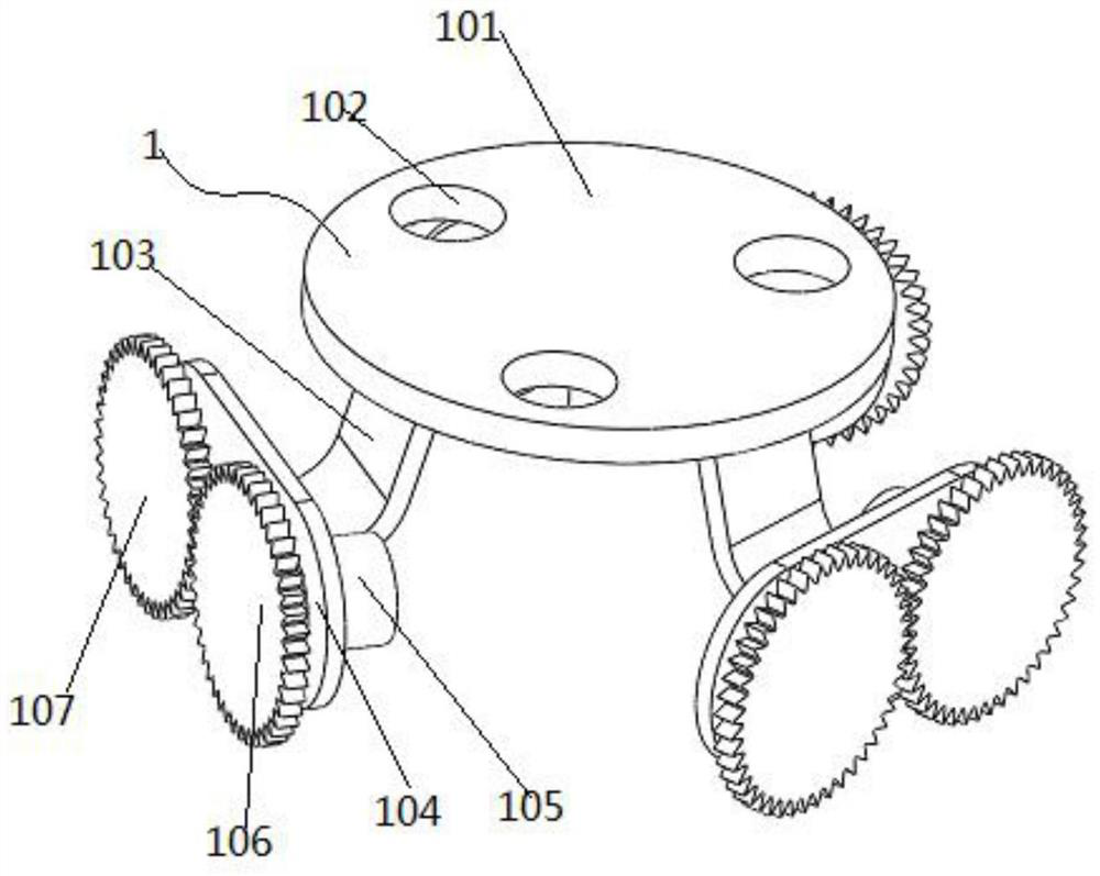
[0026] see Figure 1-6 , the present invention provides the following technical solutions: a rack arm device for lifting and extracting substrate glass, including a top seat platform assembly 1 installed on the frame arm, and three sets of sets are arranged around the bottom of the top seat platform assembly 1 installed on the frame arm by rotating the shaft pin rod 2 Substrate glass lifting and extracting telescopic arm 3, the bottom of substrate glass liftin...


PUM


Abstract

The invention discloses a base plate glass lifting and extracting rack arm device. When base plate glass is in contact, lifted and extracted for use, a rack arm mounting footstock cone at the top of a rack arm mounting footstock stand assembly is fixedly connected with an end seat of an external mechanical arm through a mounting hole and a fastening bolt, and a base plate glass contact vacuum suction cup communicates with external vacuum generation equipment through a hose; a lifting driving motor drives a main driving fluted disc to rotate, and the main driving fluted disc drives an auxiliary driving fluted disc to rotate; and through driven rotation of the main driving fluted disc and the auxiliary driving fluted disc, opening and closing stretching and closing contraction movement of a base plate glass lifting and extracting telescopic arm are achieved. In this way, lifting and descending placement during contact, lifting and extracting of the base plate glass is achieved, and secondary stretching, lifting and extracting and secondary contraction movement during contact between the external mechanical arm and the base plate glass are achieved through cooperation of the base plate glass lifting and extracting rack arm device and the external mechanical arm.

Description

technical field [0001] The invention belongs to the technical field of substrate manufacturing, and in particular relates to a frame arm device for lifting and extracting substrate glass. Background technique [0002] With the continuous development and innovation of electronic technology, TFT-LCD (liquid crystal display) is widely used in various electronic products. A basic component of the device, which is a thin glass sheet produced by the float process with an extremely flat surface, the liquid crystal glass substrate is an important part of the liquid crystal flat panel display and has very broad development prospects. [0003] The existing technology has the following problems: the grinding process in the production process occupies an important position in the entire production process flow, and the quality of grinding depends on the overall grinding equipment and production process flow, but the existing G6 generation substrate grinding equipment and process flow R...

Claims


Application Information

Patent Timeline
Patent Type & Authority Applications(China)
IPC IPC(8): B24B41/00
CPCB24B41/00B24B41/005B24B41/007
Inventor 施瑞
Owner RAINBOW (HEFEI) LIQUID CRYSTAL GLASS CO LTD
Learn More