
Laboratory particle screening equipment

A screening equipment and laboratory technology, which is applied in the direction of filtration, solid separation, and separation of solids from solids with airflow, can solve the problems of reducing test efficiency, crushing, and cumbersome procedures, and achieve improved detection efficiency and operation Time-saving and labor-saving, high-efficiency screening test process

Active Publication Date: 2021-11-23
河北省高速公路延崇管理中心(河北省高速公路京雄管理中心) +1
View PDF6 Cites 0 Cited by
  • Summary
  • Abstract
  • Description
  • Claims
  • Application Information

AI Technical Summary

Problems solved by technology

[0004] At present, most of the sieving tests are manual sieving, not only the process is cumbersome, but also the efficiency is slow. At the same time, the sieving process needs to be separated and stacked according to different particle sizes, and it is very easy to confuse the specific operation.
At the same time, some tests take into account the influence of the boundary effect and size effect of the test chamber. The size of the test chamber is generally large. In order to ensure the degree of compaction, more granular materials are needed, and purely rely on manual screening or traditional screening. The equipment is used for sieving, and the particle samples that may be obtained in one sieving test are far from enough for the soil volume of the experiment, so multiple sieving is required, which seriously reduces the test efficiency
In addition, after a period of use, the particles will be broken due to the force, which will cause a certain change in the gradation. It is time-consuming and laborious to use the traditional method to detect whether the particle gradation meets the test requirements.

Method used


Image

  • Laboratory particle screening equipment
  • Laboratory particle screening equipment
  • Laboratory particle screening equipment

Examples


Embodiment Construction

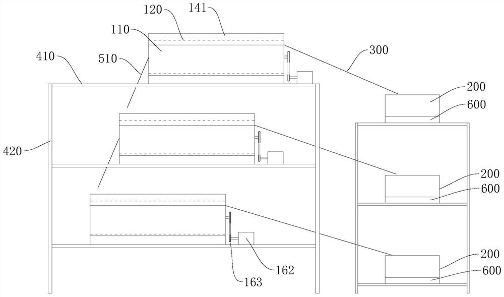
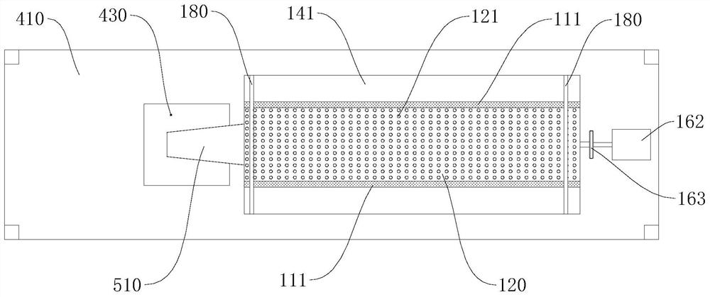
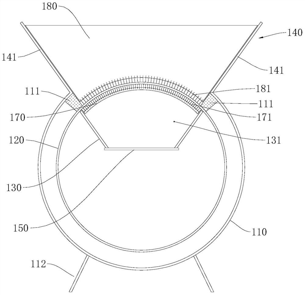
[0040] In order to make the technical problems, technical solutions and beneficial effects to be solved by the present invention clearer, the present invention will be further described in detail below in conjunction with the accompanying drawings and embodiments. It should be understood that the specific embodiments described here are only used to explain the present invention, not to limit the present invention.

[0041] Please also refer to Figure 1 to Figure 3 , the laboratory particle sieving equipment provided by the present invention is now described. The laboratory particle screening equipment includes a joint mechanism 500, a plurality of screening units 100 distributed sequentially from top to bottom and a plurality of weighing units 600, and each screening unit 100 includes an outer cylinder 110, an inner sieve Cylinder 120, sealing member 111, hopper 140, transmission mechanism 150 and connecting mechanism 500; the axis of the outer cylinder 110 is set perpendicu...


PUM


Abstract

The invention provides laboratory particle screening equipment. The laboratory particle screening equipment comprises a connecting mechanism, multiple screening units and multiple weighing units, wherein each screening unit comprises a corresponding outer barrel, a corresponding inner screening barrel, a corresponding sealing piece, a corresponding hopper, a corresponding conveying mechanism and a corresponding connecting mechanism; the inner screening barrels are arranged in the outer barrels, the axes of the inner screening barrels are parallel to the axes of the outer barrels, and the inner screening barrels have the freedom degrees of rotating around the axes of the inner screening barrels, and are provided with screen holes; the apertures of the screen holes in the screening units on the upper layers are larger than those of the screen holes in the screening units on the lower layers; the sealing pieces are arranged between openings of the outer barrels and the outer wall surfaces of the inner screening barrels; the hoppers are arranged at the openings of the outer barrels; the conveying mechanisms are arranged in the inner screening barrels; the connecting mechanisms are in butt joint with the conveying mechanisms; and the weighing units is in butt joint with the hoppers. According to the laboratory particle screening equipment, manual screening is not needed, time and labor are saved in operation, and screened particles with various particle sizes can be collected respectively, so that the screening test process is more efficient.

Description

technical field [0001] The invention belongs to the technical field of screening equipment, and in particular relates to a laboratory particle screening equipment. Background technique [0002] Indoor experiments are an important part of scientific research. With the gradual deepening of experts and scholars' research on some issues, the research on indoor experiments is developing towards refinement. In order to more realistically simulate and restore the stress state of each object in the actual project, it is often necessary to use soil media to complete the test. Regarding the soil medium, many test results have confirmed that the impact of particle size on the test cannot be ignored. Although many experts and scholars have conducted a large number of experimental studies on the influence of particle size pairing test results, the impact mechanism of particle size pairing test and the mechanical behavior of particles between gradations are still unclear, so a large numb...

Claims


Application Information

Patent Timeline
Patent Type & Authority Applications(China)
IPC IPC(8): B07B9/00B07B1/22B07B1/42B07B1/46B07B1/52
CPCB07B9/00B07B1/22B07B1/42B07B1/46B07B1/526B07B1/522B07B2201/04
Inventor 杨广庆张孟强于建游左政彭亚荣张志刚刘志忠牛笑笛李丹枫黄一凡李婷王志杰王贺
Owner 河北省高速公路延崇管理中心(河北省高速公路京雄管理中心)
Learn More