Energy-saving automatic paint slag fishing integrated equipment

An energy-saving, paint slag technology, applied in the direction of using liquid separating agent, chemical instruments and methods, and filtration circuits, can solve problems such as damage to human organs, combustion, explosion, and reduction of regional environmental function levels, so as to improve work efficiency, The effect of easy installation

Pending Publication Date: 2021-11-23
江苏瑞德斯环保科技有限公司
View PDF0 Cites 0 Cited by
  • Summary
  • Abstract
  • Description
  • Claims
  • Application Information

AI Technical Summary

Problems solved by technology

[0002] The spraying industry produces a large amount of falling paint in the producing countries. The amount of falling paint varies according to the process method, workpiece structure and construction environment. At present, the most commonly used method is spraying. In a windless indoor environment, the falling paint will change with time. The water curtain flows into the collection pool together. After a period of time, paint slag is formed or precipitated or floated in the collection pool. Due to the strong adhesion of the paint slag, it is easy to adhere, which brings many difficulties to the removal of paint slag.
[0003] When the traditional equipment for removing paint slag is used, most of them are collected in multiple pools, and they need to be cleaned manually every six months. Hazardous waste discharged and stored randomly will pollute the water body and soil under the long-term infiltration and diffusion of rainwater and groundwater, and reduce the environmental function level of the area. Cause poisoning, or cause dangerous events such as combustion and explosion; long-term hazards include long-term poisoning, carcinogenicity, teratogenicity, and mutagenicity caused by repeated exposure

Method used


Image

  • Energy-saving automatic paint slag fishing integrated equipment
  • Energy-saving automatic paint slag fishing integrated equipment
  • Energy-saving automatic paint slag fishing integrated equipment

Examples


Embodiment Construction

[0025] The technical solutions in the embodiments of the present invention will be clearly and completely described below with reference to the accompanying drawings in the embodiments of the present invention. Obviously, the described embodiments are only a part of the embodiments of the present invention, but not all of the embodiments. Based on the embodiments of the present invention, all other embodiments obtained by those of ordinary skill in the art without creative efforts shall fall within the protection scope of the present invention.

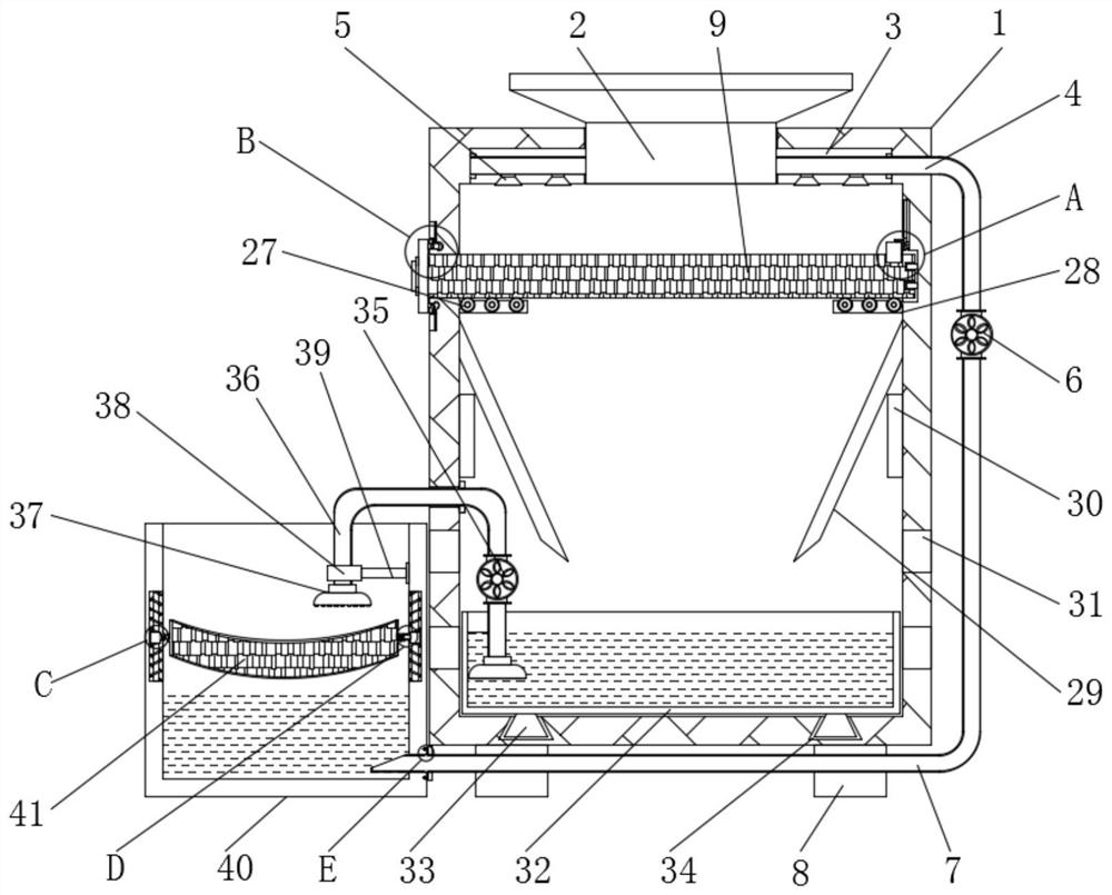
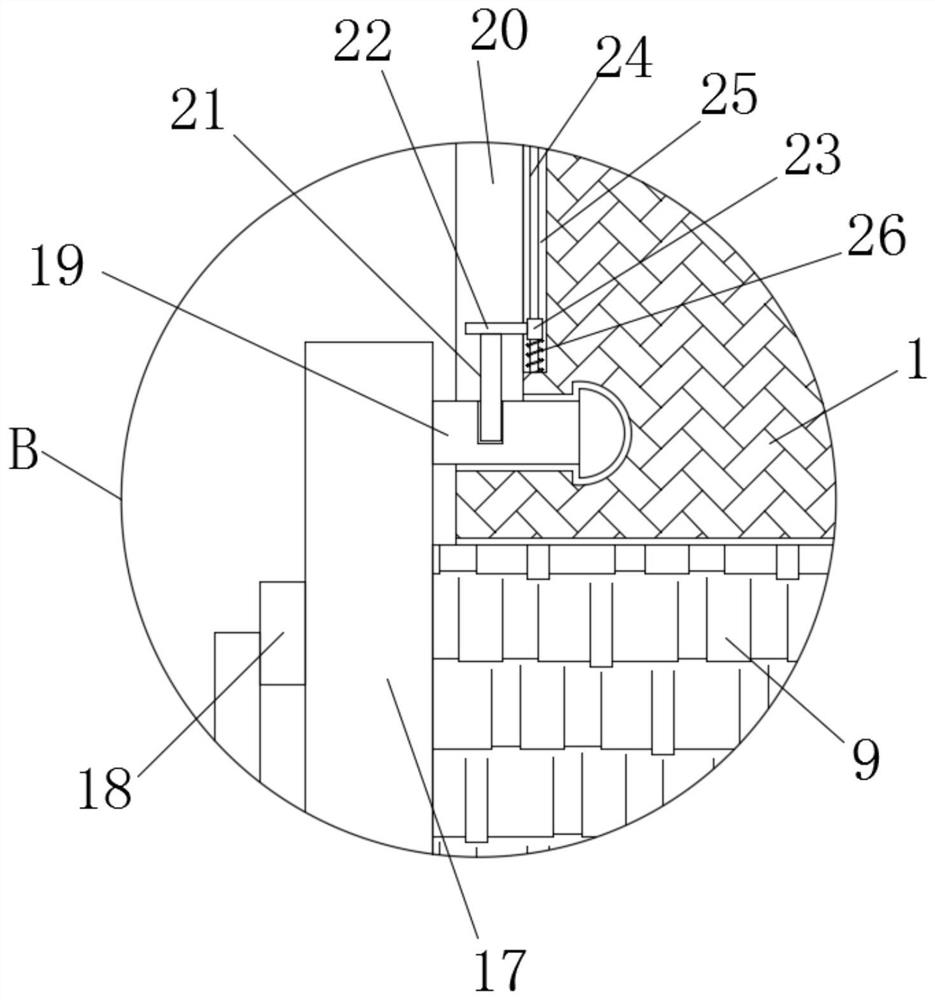
[0026] like Figure 1-6 As shown, the embodiment provided by the present invention: an energy-saving automatic paint slag fishing integrated equipment, including a paint residue fishing equipment main body 1, a feeding port 2, a supporting bottom block 8, a ventilation hole 31 and a bearing water tank 40, A feeding port 2 is fixedly connected to the top middle of the main body 1 of the paint slag equipment device, and two sets of vent...


PUM


Abstract

The invention relates to the technical field of paint slag fishing equipment, in particular to energy-saving automatic paint slag fishing integrated equipment which comprises a paint slag fishing equipment main body, a feeding port, a supporting bottom block, an air hole and a bearing water tank. A feeding hole is fixedly connected to the middle part of the top end of the paint slag fishing equipment main body. Two sets of air holes are symmetrically formed in the lower end of the middle of the outer wall of the paint slag fishing equipment main body, two sets of supporting bottom blocks are symmetrically installed on the two sides of the bottom end of the paint slag fishing equipment main body, and a bearing water tank is installed on the outer wall of the left side of the paint slag fishing equipment main body through a circulating screening mechanism. According to the paint slag fishing equipment, the activated carbon sieving plate and the paint slag fishing equipment body can be relatively conveniently installed, harmful gas on the inner side of air on the inner wall of the paint slag fishing equipment body can be effectively diluted, and meanwhile solid paint slag can be effectively sieved; and the working efficiency of the device in the using process can be effectively improved.

Description

technical field [0001] The invention relates to the technical field of paint slag fishing equipment, in particular to an energy-saving automatic paint slag fishing integrated equipment. Background technique [0002] The spraying industry produces a large amount of falling paint in the production country. The amount of paint falling varies according to the process method, workpiece structure and construction environment. At present, the most commonly used method is the spraying construction method. In a windless indoor environment, the falling paint will follow. The water curtain flows into the collection tank together. After a period of time, paint slag is formed or precipitated or floated in the collection tank. Due to the strong adhesion of paint slag, it is easy to adhere, which brings many difficulties to the extraction of paint slag. [0003] When the traditional paint slag extraction equipment is used, most of them are collected in multiple pools, which need to be clea...

Claims


Application Information

Patent Timeline
IPC IPC(8): B01D47/06B01D36/04
CPCB01D47/06B01D36/04
Inventor 徐立农吴琦孙波何旭红
Owner 江苏瑞德斯环保科技有限公司
Why Eureka
Try Eureka