A kind of control method of synchronous accelerator

A synchrotron and control method technology, applied in the direction of magnetic resonance accelerators, accelerators, electrical components, etc., can solve the problems of single energy platform, low beam utilization rate, long energy switching time, etc., to reduce losses and increase triangle area effect

Active Publication Date: 2022-05-20
TSINGHUA UNIV
View PDF7 Cites 0 Cited by
  • Summary
  • Abstract
  • Description
  • Claims
  • Application Information

AI Technical Summary

Problems solved by technology

[0003] At present, the way of switching and extracting the beam energy adopted by the synchrotron is usually as follows: figure 1 As shown, this method has several disadvantages: First, there is only a single energy platform in each cycle, and only a single-energy beam can be extracted, and the energy switching of the extracted beam can only be switched between cycles, so in After the extraction of the previous cycle is completed, the magnetic field drop of the magnet needs to be reset to the initial value, and then re-inject the beam current to accelerate it to a new energy platform. Every time switching energy requires the process of magnetic field reset and re-acceleration, energy switching The time is long; the second is that the utilization rate of the beam is low. When the number of particles required by a certain energy reaches the requirement, the remaining beam in the synchrotron will be lost due to energy switching and will not be used.
However, the above patents do not mention the control of beam loss in the process of multi-energy slow extraction

Method used


Image

  • A kind of control method of synchronous accelerator
  • A kind of control method of synchronous accelerator
  • A kind of control method of synchronous accelerator

Examples


Embodiment Construction

[0019] A synchrotron is an accelerator device that uses radio frequency electric fields to accelerate charged particles on a circular path. Charged particles undergo cyclotron motion in a synchrotron.

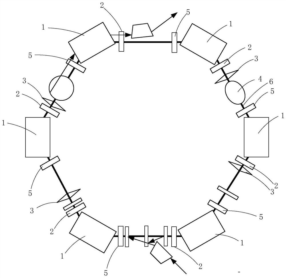
[0020] In this example, if figure 2 As shown, the synchrotron includes a ring path 6, a high frequency cavity 4, a radio frequency excitation device and multiple groups of confinement magnets. A high frequency cavity 4 (RF cavity) is arranged on the circular path 6 . Multiple groups of confining magnets are distributed around the circumference of the annular path 6 . Each group of confinement magnets includes dipole iron 1 , focusing quadrupole iron 2 , defocusing quadrupole iron 5 and hexapole iron 3 .

[0021] The magnetic field of the dipole iron 1 is used to deflect the particles, making the charged particles do gyroscopic motion. The magnetic fields of the focusing quadrupole 2 and the defocusing quadrupole 5 are used to focus the beam in the transverse direction to m...


PUM


Abstract

A control method of a synchrotron, which includes: accelerating charged particles to the first extraction energy through a radio frequency electric field; increasing the voltage value of the radio frequency electric field to a deceleration voltage value; changing the synchronous phase of the radio frequency electric field so that the radio frequency electric field is applied to the charged particles and moves The force in the opposite direction maintains the deceleration voltage value so that the energy of the charged particles decreases until the energy of the charged particles decreases from the first extracted energy to the second extracted energy. The voltage value of the radio frequency electric field is raised first, and the voltage value of the radio frequency electric field is kept at the higher voltage value to decelerate the charged particles, which can reduce the longitudinal loss caused by the beam current during the process of reducing to the second extraction energy. While increasing the voltage of the radio frequency electric field, the magnetic field intensity of the focusing quadrupole iron is increased or the magnetic field intensity of the defocused quadrupole iron is decreased, and the magnetic field intensity of the hexapole iron is decreased, which can reduce the beam current in the process of reducing to the second extraction energy Losses caused by the lateral direction.

Description

technical field [0001] This paper relates to accelerator technology, especially a control method of synchrotron. Background technique [0002] Usually, a synchrotron can only extract a single-energy beam within one cycle, and switching the extracted energy can only be done between cycles. like figure 1 As shown, after the beam is accelerated to a certain energy, keep the frequency of the magnet and the high-frequency cavity unchanged to ensure that the energy of the particles remains unchanged. The beam is extracted under this energy platform. If the extracted energy needs to be changed, in the next cycle Accelerate the beam to a new energy and lead it out under a new energy platform, figure 1 It takes three cycles for the energy of the center-extracted beam to change from E1 to E2 and E3 in turn. If beam currents of N energies are required, at least N cycle periods are required to realize them. [0003] At present, the way of switching and extracting the beam energy ado...

Claims


Application Information

Patent Timeline
Patent Type & Authority Patents(China)
IPC IPC(8): H05H13/04
CPCH05H13/04
Inventor 郑曙昕叶文博姚红娟王学武
Owner TSINGHUA UNIV
Why Eureka
Try Eureka