


Quick Research
Generate reliable direction feasibility study reports for your R&D in just a few steps.

Technical Q&A
Discover and master advanced knowledge NOW. Basics, ideas, possibilities, all at once.

Find Solutions
As an expert in R&D theories, this can generate solutions to your technical problems instantly.

Evaluate Feasibility
Analyze your overall solution with one click, know your potential R&D risks in advance.

Monitor Landscape
Get weekly tech updates, stay abreast of the latest tech innovations and key insights.
Control circuit and control method for power switching device
A technology for power switching and control circuits, applied in circuit devices, battery circuit devices, circuits, etc., can solve the problems of high power, low current during holding, and large start-up inrush current, and achieve low-cost effects.
- Summary
- Abstract
- Description
- Claims
- Application Information
AI Technical Summary
Problems solved by technology
Method used
Image

Examples
Embodiment 1
[0042] When the grid is powered:
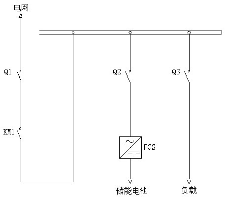
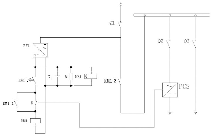
[0043] Such as figure 2 As shown, a control circuit for a power switching device includes a wind power storage backup power system, the wind power storage backup power system includes an energy storage converter PCS, and also includes: a wind power storage backup power control circuit: power-on delay Relay KA1, switching power supply PW1, energy storage capacitor C1, energy storage system control switching relay K and relay KM1, where:
[0044]The first output end of the switching power supply PW1 is connected to the first input end of the energy storage capacitor C1 for charging the energy storage capacitor C1; the first output end of the energy storage capacitor C1 is connected to the relay KM1; the two ends of the energy storage capacitor C1 A power-on delay relay KA1 is connected in parallel; the second output terminal of the switching power supply PW1 is connected to the input terminal of the power-on delay relay contact KA1-1; the out...
Embodiment 2
[0056] When the power grid is under low voltage ride through:
[0057] Such as figure 2 As shown, a control circuit for a power switching device includes a wind power storage backup power system, the wind power storage backup power system includes an energy storage converter PCS, and also includes: a wind power storage backup power control circuit: power-on delay Relay KA1, switching power supply PW1, energy storage capacitor C1, energy storage system control switching relay K and relay KM1, where:
[0058] The first output end of the switching power supply PW1 is connected to the first input end of the energy storage capacitor C1 for charging the energy storage capacitor C1; the first output end of the energy storage capacitor C1 is connected to the relay KM1; the two ends of the energy storage capacitor C1 A power-on delay relay KA1 is connected in parallel; the second output terminal of the switching power supply PW1 is connected to the input terminal of the power-on dela...
Embodiment 3
[0076] Such as figure 2 Shown: When the grid is powered off:
[0077] A control circuit for a power switching device, including a wind power storage backup power system, the wind power storage backup power system includes an energy storage converter PCS, and also includes: a wind power storage backup power control circuit: power-on delay relay KA1, Switching power supply PW1, energy storage capacitor C1, energy storage system control switching relay K and relay KM1, where:
[0078] The first output end of the switching power supply PW1 is connected to the first input end of the energy storage capacitor C1 for charging the energy storage capacitor C1; the first output end of the energy storage capacitor C1 is connected to the relay KM1; the two ends of the energy storage capacitor C1 A power-on delay relay KA1 is connected in parallel; the second output terminal of the switching power supply PW1 is connected to the input terminal of the power-on delay relay contact KA1-1; the...
PUM
 Abstract
Description
Claims
Application Information
 - R&D Engineer
- R&D Manager
- IP Professional
- Industry Leading Data Capabilities
- Powerful AI technology
- Patent DNA Extraction
Browse by: Latest US Patents, China's latest patents, Technical Efficacy Thesaurus, Application Domain, Technology Topic, Popular Technical Reports.
© 2024 PatSnap. All rights reserved.Legal|Privacy policy|Modern Slavery Act Transparency Statement|Sitemap|About US| Contact US: help@patsnap.com