Process for manufacturing sealed automotive electrical fuse box

A technology of fuses and crafts, applied in the field of fuses

Pending Publication Date: 2021-11-19
LITTELFUSE INC
View PDF0 Cites 1 Cited by
  • Summary
  • Abstract
  • Description
  • Claims
  • Application Information

AI Technical Summary

Problems solved by technology

While fuses are included, it is an ongoing challenge in this extreme environment to ensure that the fuses are not damaged, such as by dust or moisture entering the electrical fuse box.

Method used


Image

  • Process for manufacturing sealed automotive electrical fuse box
  • Process for manufacturing sealed automotive electrical fuse box
  • Process for manufacturing sealed automotive electrical fuse box

Examples


Embodiment Construction

[0013] A method of manufacturing a dust and moisture resistant fuse assembly according to the present disclosure will now be described more fully hereinafter with reference to the accompanying drawings, in which preferred embodiments of the disclosure are presented. However, the methods of the present disclosure may be implemented in many different forms and should not be construed as limited to the embodiments set forth herein. Rather, these embodiments are provided so that this disclosure will convey certain exemplary aspects of the method to those skilled in the art.

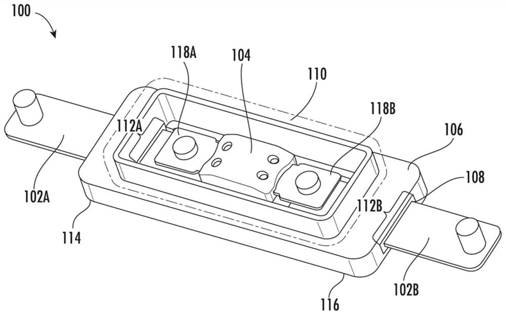
[0014] refer to figure 1 , shows a representative diagram of an electrical fuse assembly 100 according to an exemplary embodiment. Electrical fuse assembly 100 (hereinafter "fuse assembly 100") generally includes two bus bars 102A and 102B (collectively "bus bars 102"), fuse housing 104, terminals 118A, 118B, base 106, sealant 108 and cover 110 . Base 106 and cover 110 form an enclosure for the fusible ele...


PUM

PropertyMeasurementUnit
thicknessaaaaaaaaaa

Abstract

A fuse assembly including a fuse connected to two busbars, an injection molded base and an injection molded cover. The busbars are powder-coating with a powder-based adhesive or adhesion promoter, then cured in an oven. The busbars are then placed in the cavity image of an injection molding apparatus. Plastic is heated to a liquid form and injected into the cavity image. The resulting injection molded base is resistant to both dust and water, protecting the fuse inside.

Description

technical field [0001] Embodiments of the present disclosure relate to the field of fuses, and more particularly, to a dust-proof and moisture-proof fuse enclosure. Background technique [0002] Fuses are used in a variety of circuits to protect electronic components from overcurrent events. Fuses come in many shapes and sizes. For some applications, such as circuit protection in extreme environments, fuses can be contained in enclosed structures, known as electrical fuse boxes. While fuses are included, it is a constant challenge in this extreme environment to ensure that the fuses are not damaged, such as by dust or moisture entering the electrical fuse box. [0003] With regard to these and other considerations, the present improvements may be useful. Contents of the invention [0004] This Summary is provided to introduce a selection of concepts in a simplified form that are further described below in the Detailed Description. This Summary is not intended to identi...

Claims


Application Information

Patent Timeline
Patent Type & Authority Applications(China)
IPC IPC(8): H01H69/02B29C45/14
CPCH01H69/02B29C45/14008B29C45/1671B29C2045/14868B29C45/14639B29C45/14311B29C2045/14319B29C45/73B29L2031/36H01H85/175H01H85/20H01H85/201H01H85/2045H01H2085/2055H01H2085/206H01H2229/047H01H2229/048
Inventor 迈克尔·斯克日普扎克基思·尤兹维克
Owner LITTELFUSE INC
Why Eureka
Try Eureka