
RJ45 high-speed signal conversion device

A RJ45, high-speed signal technology, applied in the direction of coupling device, two-part connecting device, connecting device components, etc., can solve problems such as signal attenuation, and achieve the effect of increasing the core spacing, reducing transmission interference, and eliminating signal crosstalk.

Pending Publication Date: 2021-11-16
ZHEJIANG HEPINGGE XINXIJISHU
View PDF13 Cites 1 Cited by
  • Summary
  • Abstract
  • Description
  • Claims
  • Application Information

AI Technical Summary

Problems solved by technology

[0004] In order to overcome the signal attenuation problem of RJ45 in the interface in the current international standard, the present invention provides an RJ45 high-speed signal conversion device to reduce crosstalk in signal transmission

Method used


Image

  • RJ45 high-speed signal conversion device
  • RJ45 high-speed signal conversion device
  • RJ45 high-speed signal conversion device

Examples


Embodiment 1

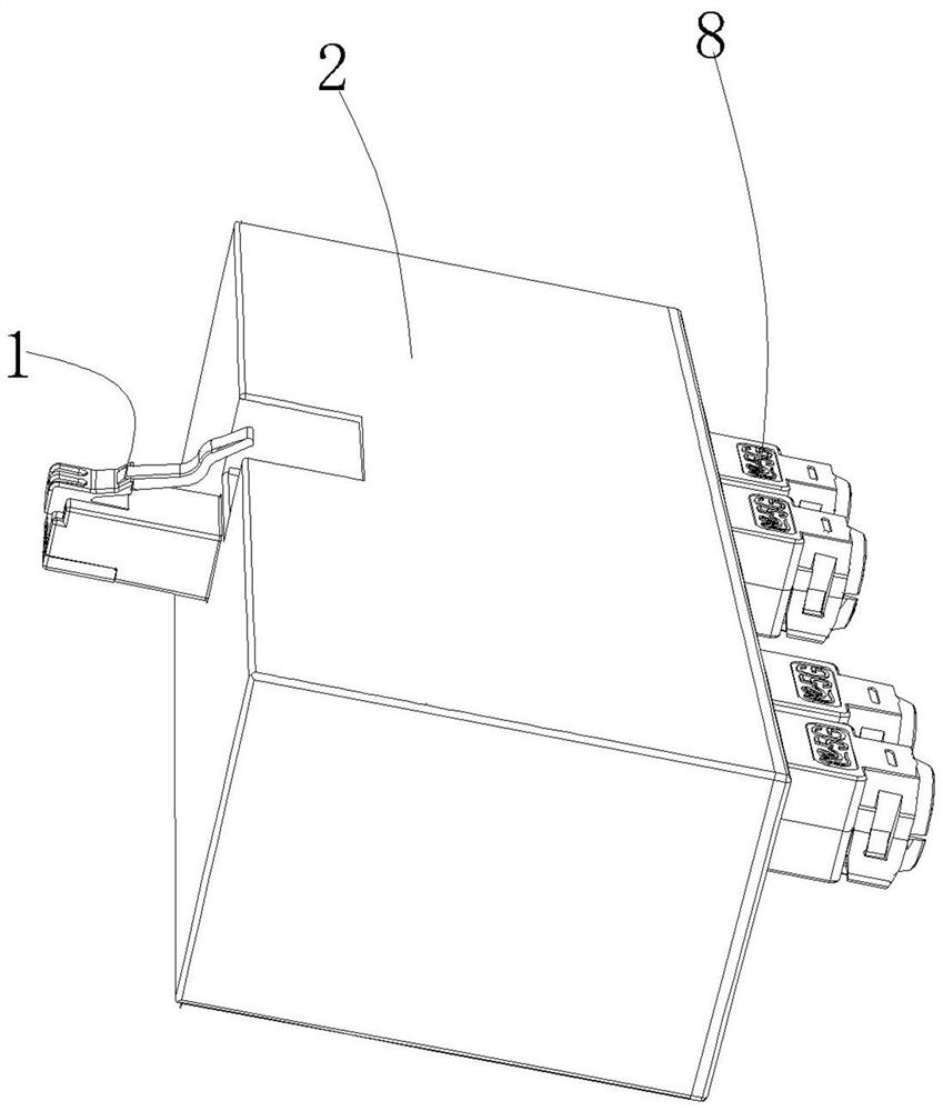
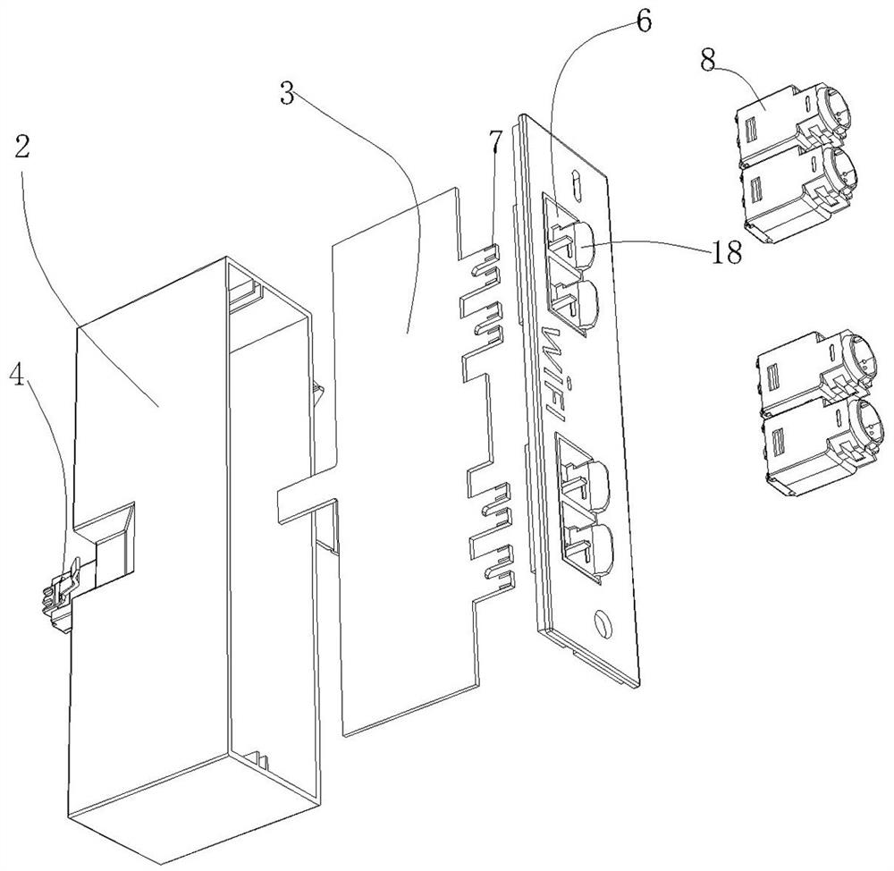
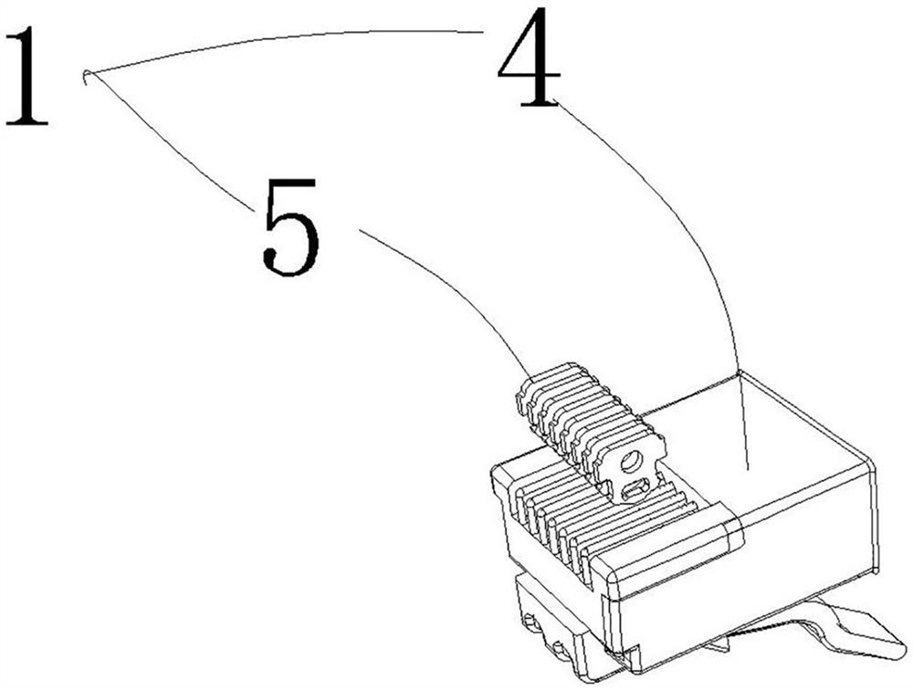
[0020] Such as Figure 1 to Figure 4 Shown: an RJ45 high-speed signal conversion device, including an RJ45 head 1, and a housing 2, characterized in that it also includes a circuit board 3, and the RJ45 head 1 includes a plastic shell 4 and a metal sheet in contact with the RJ45 socket 6 pins 5. The part of the circuit board 3 extends into the RJ45 head 1, and the metal sheet 5 is in contact with the line on the circuit board 3 for signal transmission.

[0021] The rear end of the housing 2 is provided with a socket 6, and the circuit board 3 is provided with a gold finger 7, and the gold finger 7 is located in the socket 6;

[0022] Also includes a plug 8, the plug 8 includes the shell 2 body and the wiring core 82 located in the shell 2, the wiring core 82 is provided with a broken wire slot 821, and the broken wire slot 821 is provided with a broken wire connection A piece 822, the side of the housing 2 is provided with a flexible connection part 823, the flexible connecti...

Embodiment 2

[0026] Such as Figure 5 As shown: this embodiment is an improvement based on Embodiment 1, and also includes a fixing device, the fixing device includes a fixing frame 9 located on the side of the housing 2, and the fixing frame 9 includes at least one piece of the first piece parallel to the direction of the RJ45 head 1. One piece of packaging body 10, the first piece of packaging body 10, the second piece of packaging body 11 is connected to the lower edge of the first piece of packaging body 10, and the second piece of packaging body 11 is provided with a mounting hole 19.

Embodiment 3

[0028] Such as Image 6 As shown: this embodiment is an improvement based on Embodiment 1, the metal sheet 5 includes a first contact surface 13 whose upper end is in contact with the contact pin of the RJ45 socket, the middle part of the lower end of the metal sheet 5 is hollowed out, and the metal sheet 5 The lower end surface is used to contact the second contact surface 14 of the circuit board 3 , and the two ends of the second contact surface 14 are arc surfaces. Limiting shoulders 15 protrude from both sides of the metal sheet 5 .


PUM


Abstract

The invention relates to the field of communication, in particular to an RJ45 high-speed signal conversion device. The device comprises an RJ45 head and a shell and further comprises a circuit board; the RJ45 head comprises a plastic shell and a metal sheet in contact with an RJ45 socket pin, and part of the circuit board extends into the RJ45 head. The device also comprises a plug, and the plug comprises an outer shell and a wiring core located in the outer shell; a wire breaking groove is formed in the wiring core, a wire breaking connecting piece is arranged in the wire breaking groove, a flexible connecting part is arranged on the side face of the outer shell and corresponds to the wire breaking groove of the wiring core, and a wire pressing block corresponding to the wire breaking groove is arranged on the inner side of the flexible connecting part; and the front end of the wiring core is provided with an open slot for inserting a circuit board. The device adapts to the international general RJ45 standard, is convenient to replace, and breaks through the conventional network transmission limit; a left-right separated wiring mode is adopted to increase the distance between wire cores and reduce transmission interference; a pin structure of a conventional RJ45 interface is removed, and signal crosstalk caused by the pin is avoided; the contact area is larger, and the problem of poor contact caused by oxidation of the contact pin is effectively prevented.

Description

technical field [0001] The invention is designed in the field of communication, especially the signal conversion device based on RJ45. Background technique [0002] RJ45 is a kind of information (that is, communication outlet) connector in the wiring system. The connector is composed of a plug (joint, crystal head) and a socket (module). The plug has 8 grooves and 8 contacts. RJ is the abbreviation of Registered Jack, which means "registered socket". In FCC (Federal Communications Commission Standards and Regulations), RJ is the interface describing the public telecommunications network, and RJ45 of the computer network is a common name for the standard 8-bit modular interface. [0003] The terminal network wiring adopts twisted pair wires. The crosstalk of the twisted pair has been cut and reduced to the greatest extent through the winding of the two wires, but at least one set of network connectors is required to access the terminal, and the crosstalk in the connectors c...

Claims


Application Information

Patent Timeline
Patent Type & Authority Applications(China)
IPC IPC(8): H01R31/06H01R13/66H01R13/6461H01R13/02H01R24/64H01R27/02
CPCH01R31/065H01R13/665H01R13/6461H01R13/02H01R24/64H01R27/02
Inventor 周展力
Owner ZHEJIANG HEPINGGE XINXIJISHU
Learn More