Permanent magnet bonding device

A permanent magnet and bonding technology, which is applied in the manufacture of inductors/transformers/magnets, electrical components, circuits, etc., can solve the problems of permanent magnets such as easy misalignment, fragility, and low surface magnetism, and reduce the risk of collapse. The effect of high bonding precision and high safety factor

Pending Publication Date: 2021-11-16
STATE POWER INVESTMENT CORP RES INST
View PDF0 Cites 0 Cited by
  • Summary
  • Abstract
  • Description
  • Claims
  • Application Information

AI Technical Summary

Problems solved by technology

Due to the unsatisfactory performance of the permanent magnets that are first bonded and then magnetized, and the surface magnetism is low, the method of first magnetizing and then bonding is usually used. However, since each small permanent magnet has N poles and S poles after magnetization, The polarities of the bonding parts between adjacent permanent magnets are the same, so it is necessary to overcome the repulsive force between the two permanent magnets during the bonding process. The upper permanent magnet itself is a brittle material, fragile, difficult to process, and has a high degree of difficulty in operation

Method used


Image

  • Permanent magnet bonding device
  • Permanent magnet bonding device
  • Permanent magnet bonding device

Examples


Embodiment Construction

[0028] Embodiments of the invention are described in detail below, examples of which are illustrated in the accompanying drawings. The embodiments described below by referring to the figures are exemplary and are intended to explain the present invention and should not be construed as limiting the present invention.

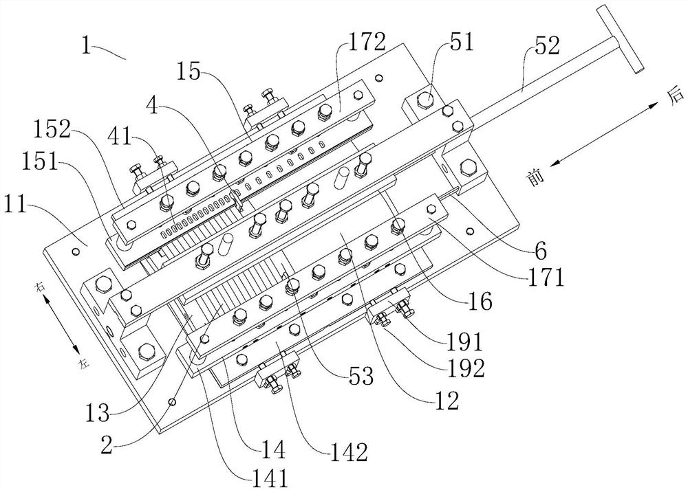
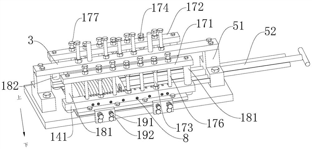
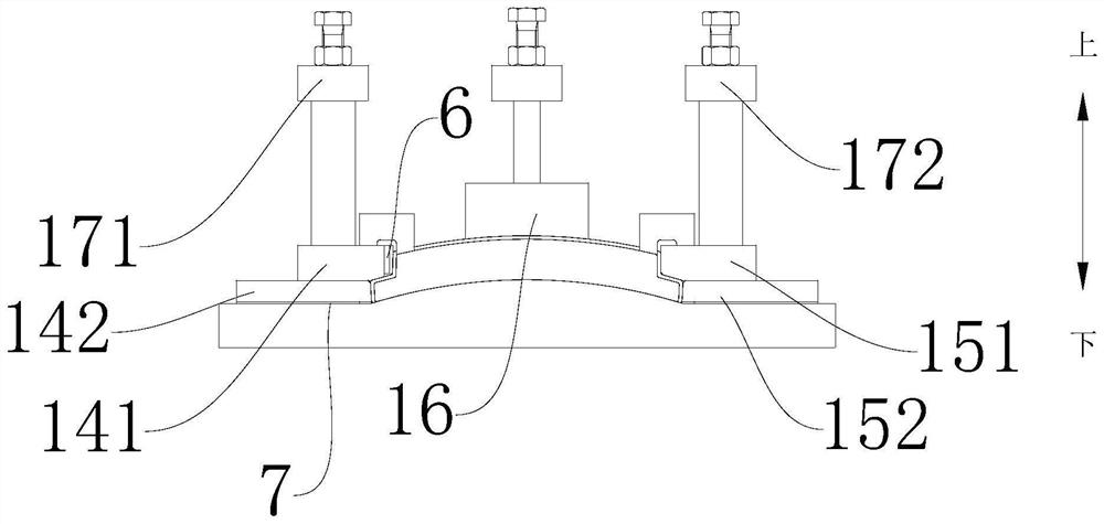
[0029] The following is based on Figure 1-3 A bonding apparatus 1 for bonding a permanent magnet 2 according to an embodiment of the present invention will be described. It should be noted that the permanent magnet 2 here refers to a small piece of permanent magnet or a permanent magnet piece, and the bonding device 1 provided in the embodiment of the present invention is used to bond several permanent magnets 2 to form a finished permanent magnet that can be used .

[0030] Such as figure 1 As shown, the bonding device 1 includes a base 11 and a sliding track assembly. The sliding track assembly is arranged on the upper surface of the base 11, the sliding t...


PUM


Abstract

The invention provides a permanent magnet bonding device, and the device comprises a base and a sliding rail assembly; the sliding rail assembly is arranged on the upper surface of the base, a sliding rail is defined by the sliding rail assembly and the upper surface of the base, the sliding rail is used for limiting a permanent magnet to slide in the first direction, and the first direction is parallel to the upper surface of the base. The sliding rail is provided with an opening facing the first direction, the sliding rail assembly comprises a stop piece opposite to the opening, a first stop piece and a second stop piece, the first stop piece and the second stop piece are located on the two sides of the sliding rail respectively, and the permanent magnet enters the sliding rail through the opening and is stopped by the stop piece. At least one of the first blocking piece and the second blocking piece is adjustable in position in the second direction perpendicular to the first direction and / or adjustable in position in the vertical direction. The bonding device has the advantages of being good in adaptability, high in bonding precision and high in safety coefficient.

Description

technical field [0001] The invention relates to the field of assembly technology, in particular to a permanent magnet bonding device. Background technique [0002] The finished permanent magnet used in the permanent magnet speed changer is usually made of multiple small pieces of permanent magnets (permanent magnet pieces) that are magnetized and bonded together. Due to the unsatisfactory performance of the permanent magnets that are bonded first and then magnetized, and the surface magnetism is low, the method of magnetizing first and then bonding is usually used. However, since each small permanent magnet has N poles and S poles after magnetization, The polarities of the bonding parts between adjacent permanent magnets are the same, so it is necessary to overcome the repulsive force between the two permanent magnets during the bonding process, and the permanent magnets are easy to misalign, which greatly affects the bonding accuracy. The upper permanent magnet itself is a...

Claims


Application Information

Patent Timeline
IPC IPC(8): H01F41/02
CPCH01F41/0253Y02E10/72
Inventor 吴先峰于成伟罗帅鲁仰辉魏立军高凌宇曹菡李高盛边卓伟严帅王晋中
Owner STATE POWER INVESTMENT CORP RES INST
Why Eureka
Try Eureka