
Calibration method, device, electronic equipment and storage medium for camera line deviation

A calibration method and line deviation technology, applied in the optical field, can solve the problems of depth data recovery failure, missing depth map, affecting the normal use of the camera, etc., to avoid efficient calibration, simplify the calibration procedure, and quickly put it back into use.

Active Publication Date: 2022-05-31
合肥的卢深视科技有限公司
View PDF5 Cites 0 Cited by
  • Summary
  • Abstract
  • Description
  • Claims
  • Application Information

AI Technical Summary

Problems solved by technology

[0004] However, the factory-made cameras will go through a series of random vibration tests, shock tests, free fall and other tests
The structure of the camera will be deformed to different degrees, so that the speckle image of the object acquired by the camera will have line deviation compared with the reference speckle image, resulting in missing or depth data in the depth map corresponding to the speckle image of the object The problem of recovery failure affects the normal use of the camera and brings great inconvenience to users

Method used


Image

  • Calibration method, device, electronic equipment and storage medium for camera line deviation
  • Calibration method, device, electronic equipment and storage medium for camera line deviation
  • Calibration method, device, electronic equipment and storage medium for camera line deviation

Examples


Embodiment Construction

[0016] In order to achieve efficient detection and calibration of the line deviation existing in the camera, the embodiment of the present invention provides a

[0017] The camera line deviation calibration method provided by the embodiment of the present invention is based on the acquired speckle pattern of the test object.

[0019] The implementation details of the camera line deviation calibration method recorded in the application will be described below in conjunction with specific embodiments.

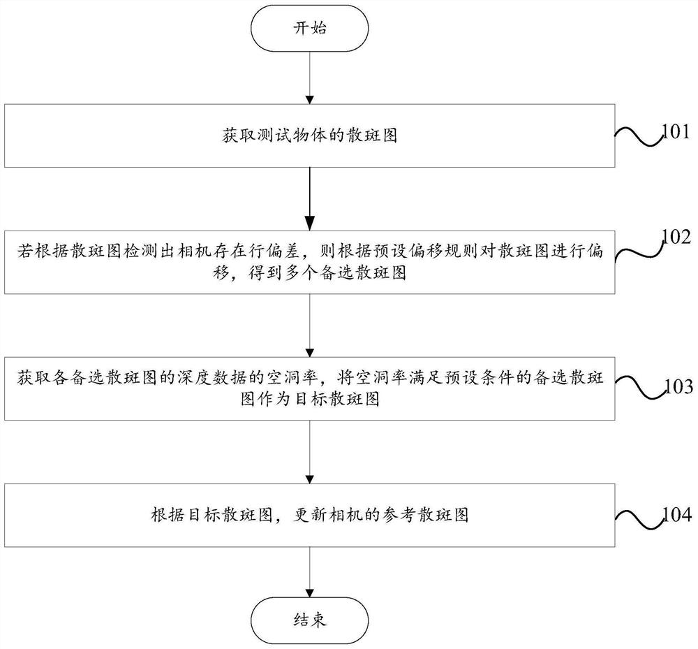
[0020] The first aspect of the embodiment of the present invention provides a camera line deviation calibration method, the specific camera calibration method [0020]

[0021] Step 101, obtain the speckle image of the test object.

[0026] In another example, after the calibration device obtains a candidate speckle pattern for each offset, the

[0027] Q

[0032] In an example, the calibration device uses the candidate speckle pattern whose void ratio satisfies a preset condition as th...


PUM


Abstract

The embodiment of the present invention relates to the field of optical technology, and discloses a camera line deviation calibration method, device, electronic equipment and storage medium. The camera line deviation calibration method includes: taking the speckle image of the test object; if the camera line deviation is detected according to the speckle image, the speckle image is offset according to the preset offset rule to obtain multiple candidate speckle images ; Obtain the void rate of the depth data of each candidate speckle map, and use the candidate speckle map whose void rate satisfies the preset condition as the target speckle map; update the reference speckle map of the camera according to the target speckle map. By using the obtained speckle image to detect the line deviation of the camera, and update the reference speckle image according to the target speckle image selected from multiple candidate speckle images obtained by migration, the automatic correction of the camera line deviation is realized. Detection and calibration avoids the problem of not being able to efficiently calibrate the camera line deviation, and simplifies the calibration procedure without introducing user operations, allowing the camera to be put back into service quickly.

Description

Camera line deviation calibration method, device, electronic device and storage medium technical field Embodiments of the present invention relate to the field of optics, and in particular to a method, device, and electronic device for calibrating camera line deviation. equipment and storage media. Background technique [0002] With the development of depth cameras, 3D vision has gradually emerged in various consumer applications. 3D vision technology can obtain Realistic 3D scene complete geometric information, using images with depth information to achieve accurate digitization of the scene, In order to achieve high-precision identification, positioning and other key functions. Depth cameras can be divided into TOF depth cameras according to their working principles. camera, binocular depth camera, structured light camera. Among them, the depth recovery time of the binocular depth camera is long, and the volume is too large to meet the actual needs Timeliness; t...

Claims


Application Information

Patent Timeline
Patent Type & Authority Patents(China)
IPC IPC(8): G06T7/33G06T5/00
CPCG06T7/337G06T5/007G06T2207/10004
Inventor 王海彬户磊刘祺昌化雪诚李东洋
Owner 合肥的卢深视科技有限公司
Learn More